Rapid taking and placing device for power battery module

A technology for power batteries and pick-and-place devices, which can be used in charging stations, electric vehicles, transportation and packaging, etc., and can solve problems such as loosening, battery damage, and affecting machine operation

Inactive Publication Date: 2021-09-10
重庆新知创科技有限公司
View PDF0 Cites 2 Cited by
  • Summary
  • Abstract
  • Description
  • Claims
  • Application Information

AI Technical Summary

Problems solved by technology

[0003] At present, the power batteries on the market need to be manually aligned before being picked and placed, or a separate placement mechanism is added to prevent the battery from being placed skewed when the battery is sucked or picked up, and the battery cannot be picked up, or It loosens or even falls after clamping, which will cause damage to the battery. Even after the suction of the battery is completed, the deflected battery will affect the operation of the machine in the next process. Therefore, a quick pick-and-place device for power battery modules is proposed to solve the above problems. proposed question

Method used


Image

  • Rapid taking and placing device for power battery module
  • Rapid taking and placing device for power battery module
  • Rapid taking and placing device for power battery module

Examples


Embodiment 1

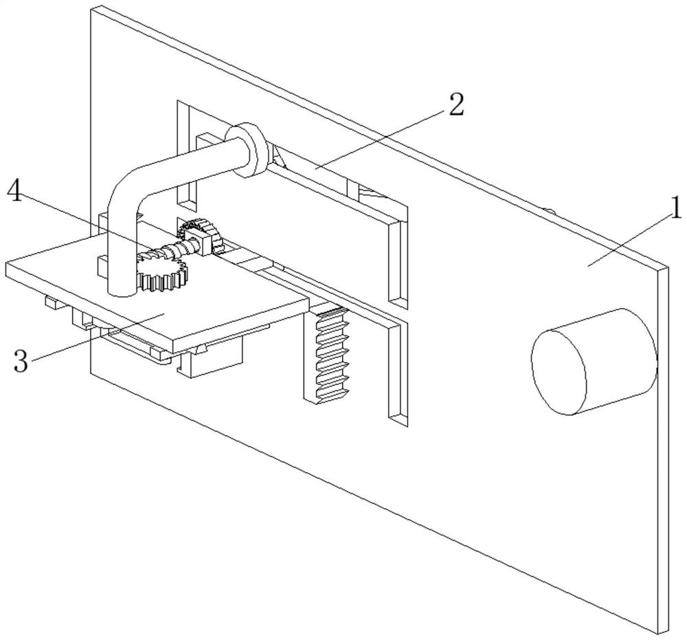
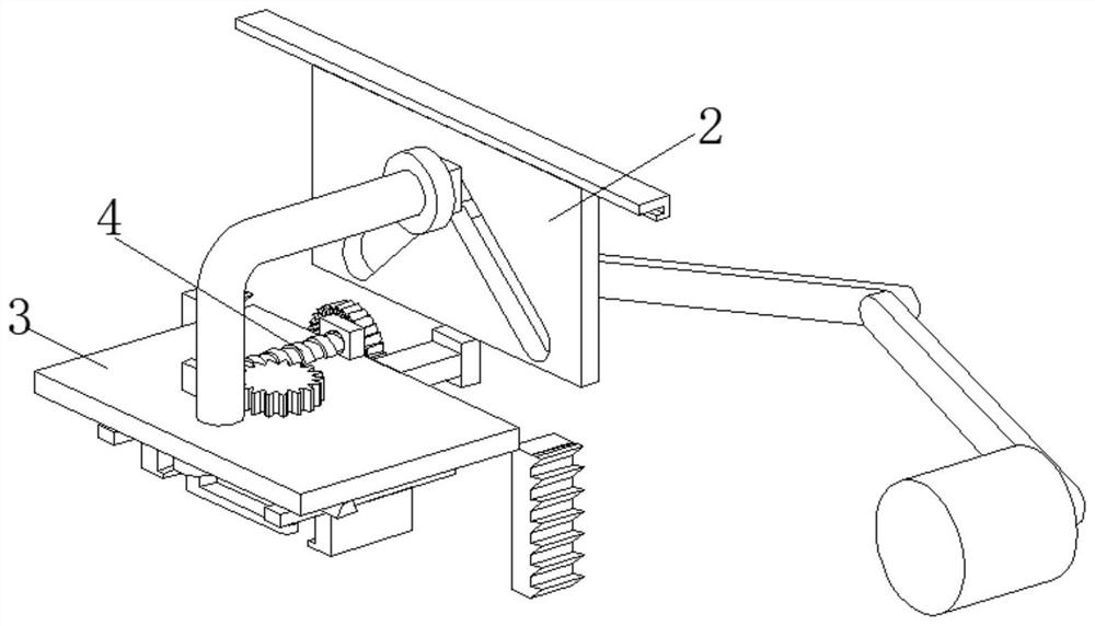
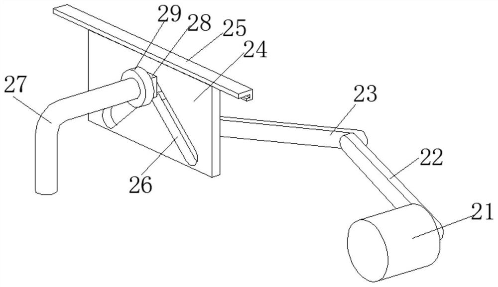
[0033] A quick pick-and-place device for a power battery module, such as Figure 1-Figure 6 As shown, including the mounting plate 1, the rear of the mounting plate 1 is provided with a working mechanism 2, the front of the mounting plate 1 is provided with a limit mechanism 3, and the surface of the limit mechanism 3 is provided with an adjustment mechanism 4; the working mechanism 2 pushes the limit The mechanism 3 moves to the left and triggers the adjustment mechanism 4, the adjustment mechanism 4 adjusts the position of the battery on the limit mechanism 3 and drives the limit mechanism 3 to clamp it up, the working mechanism 2 pushes the battery clamped by the limit mechanism 3 to move to the right And trigger the adjustment mechanism 4, and the adjustment mechanism 4 drives the limit mechanism 3 to release the battery.

[0034]Through the cooperative use of the working mechanism 2, the limit mechanism 3 and the adjusting mechanism 4, the device can be moved to the left ...

Embodiment 2

[0046] Such as Figure 5-Figure 9 As shown, on the basis of Embodiment 1, in this embodiment, the two ends of the torsion spring 344 are engaged and fixed with the limit block 342 and the inner wall of the connecting plate 341 respectively, and the rear part of the connecting plate 341 is connected with the inner wall of the mounting plate 1. Front welded fastening.

[0047] The torsion spring 344 can help the rotated limit block 342 to reset, which is convenient for the next use, but the limit block 342 cannot rotate clockwise, so the limit block 342 can drive the adjustment mechanism 4 to operate.

[0048] The adjustment mechanism 4 includes a mounting block 41, the inner wall of the mounting block 41 is rotatably connected with a worm 42, the surface of the worm 42 is meshed with a worm wheel 43, the rear end of the worm 42 is welded with a transmission gear 443, and the surface of the transmission gear 443 is meshed with teeth 441 A ratchet 44 is welded on the surface of ...


PUM


Abstract

The invention relates to the technical field of power batteries, and discloses a rapid taking and placing device for a power battery module. The device comprises a mounting plate, a working mechanism is arranged on the rear portion of the mounting plate, a limiting mechanism is arranged on the front portion of the mounting plate, and an adjusting mechanism is arranged on the surface of the limiting mechanism. According to the rapid taking and placing device for the power battery module, through cooperative use of the working mechanism, the limiting mechanism and the adjusting mechanism, a battery can be straightened while the device clamps the battery, so the battery can be conveniently clamped subsequently, and the situation that the battery is damaged due to the fact that the battery deviates and then falls off after being clamped is prevented; through a supporting spring between an inner plate and an outer plate in the limiting mechanism, the device can adapt to batteries of different sizes when clamping the batteries, when the sizes of the batteries are large, the device can clamp the batteries excessively, but the inner plate and the outer plate can displace, the batteries are prevented from being damaged by clamping, and the application range of the device is greatly widened.

Description

technical field [0001] The invention relates to the technical field of power batteries, in particular to a quick pick-and-place device for power battery modules. Background technique [0002] The power battery is the power supply that provides the power source for the tool. It mostly refers to the battery that provides power for electric vehicles, electric trains, electric bicycles, and golf carts. Lead-acid batteries, open tubular lead-acid batteries and lithium iron phosphate batteries. [0003] At present, the power batteries on the market need to be manually aligned before being picked and placed, or a separate placement mechanism is added to prevent the battery from being placed skewed when the battery is sucked or picked up, and the battery cannot be picked up, or It loosens or even falls after clamping, which will cause damage to the battery. Even after the suction of the battery is completed, the deflected battery will affect the operation of the machine in the next...

Claims


Application Information

Patent Timeline
Patent Type & Authority Applications(China)
IPC IPC(8): B60L53/80
CPCB60L53/80Y02T10/70Y02T10/7072
Inventor 陈城
Owner 重庆新知创科技有限公司
Why Eureka
Try Eureka