
Lamp part subpackaging equipment

A technology of packaging and parts, which is applied in the field of lighting parts packaging equipment, can solve the problem that there is no way to adjust the size of lighting parts according to the actual use

Active Publication Date: 2021-09-10
惠州兴通成机电技术有限公司
View PDF19 Cites 0 Cited by
  • Summary
  • Abstract
  • Description
  • Claims
  • Application Information

AI Technical Summary

Problems solved by technology

[0002] For example, the patent number is CN201710727371.3, a welding mold for lamp parts processing, including a conveying unit, a welding unit arranged on the rear side of the conveying unit, a cooling unit, and an exhaust gas recovery unit arranged between the welding unit and the cooling unit; The welding unit includes a bracket and a welding device; the conveying unit includes a first conveying device and a second conveying device, and the first conveying device includes a left conveying platform, a right conveying platform and is used to adjust the distance between the left and right conveying platforms. The displacement adjustment device of the spacing size, the left transmission platform and the right transmission platform are respectively provided with a transmission part; the second transmission device includes two symmetrically arranged support arms and a conveyor belt arranged on the support arms, but the technical solution The disadvantage is that there is no way to adjust the size of the lamp parts that can be carried according to the actual use

Method used


Image

  • Lamp part subpackaging equipment
  • Lamp part subpackaging equipment
  • Lamp part subpackaging equipment

Examples


specific Embodiment approach 1

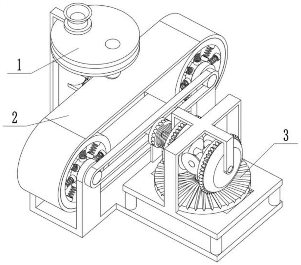
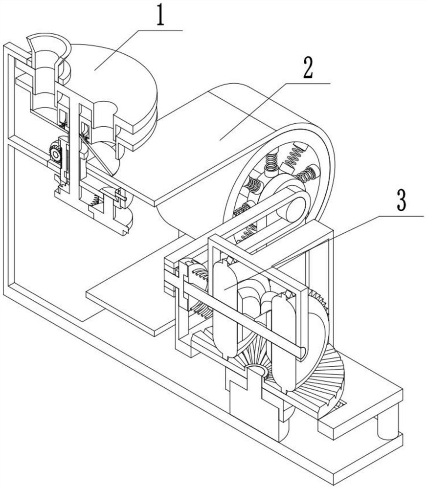
[0029] Combine below Figure 1-12In this embodiment, a lamp parts subpackaging device includes a subpackaging assembly 1 , a carrying assembly 2 , and a driving assembly 3 . The subpackaging assembly 1 is connected to the carrying assembly 2 , and the carrying assembly 2 is connected to the driving assembly 3 .

specific Embodiment approach 2

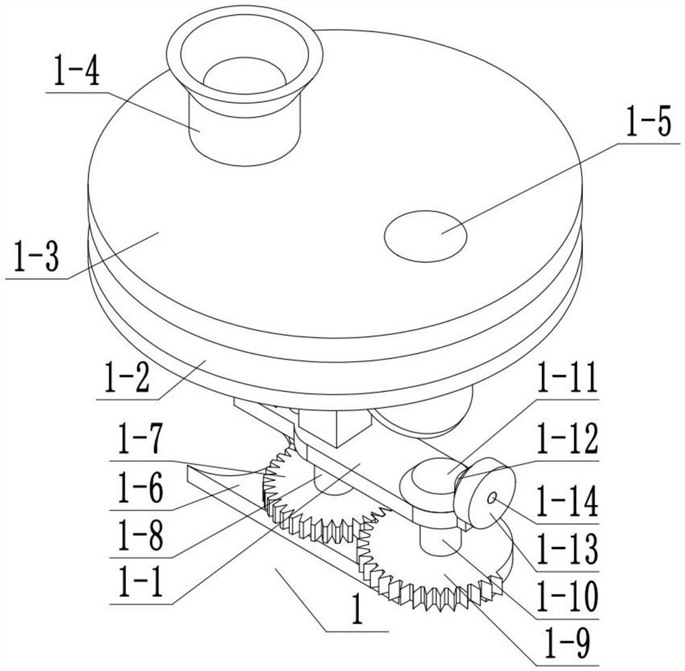
[0031] Combine below Figure 1-12 Describe this embodiment, this embodiment will further explain Embodiment 1, the subpackage assembly 1 includes a subpackage bracket 1-1, a middle drive plate 1-2, an upper drive plate 1-3, and a feed pipe 1-4 , Feeding casing 1-5, matching plate 1-6, straight gear one 1-7, straight gear shaft one 1-8, half straight gear two 1-9, straight gear shaft two 1-10, bevel gear one 1 -11, bevel gear 2 1-12, driving friction wheel 1-13, bevel gear shaft 1 1-14, driving rotating rod 1-15, adjusting straight gear 1-16, flipping cover 1-17, passive matching rod 1 -18, expansion sleeve 1-19, driving boss 1-20, driving groove 1-21, adjusting rack 1-22, manual rotating rod 1-23, inner end clamping rod 1-24, inner end clamping Rod push spring one 1-25, inner end card slot one 1-26, semicircular boss 1-27, the material casing 1-5 is arranged on the upper end drive plate 1-3, and the feeding pipe 1-4 Connected with the material sleeve 1-5, the spur shaft 1-8 ...

specific Embodiment approach 3

[0034] Combine below Figure 1-12 Describe this embodiment, this embodiment will further explain Embodiment 1, the contact surface between the middle end drive plate 1-2 and the spur shaft 1-8 is non-circular, and the turning cover 1-17 and the expansion sleeve 1 The specification of -19 is adapted.


PUM


Abstract

The invention relates to the field of lamps, in particular to lamp part subpackaging equipment. Single separation of lamp parts can be realized, and single packaging of the lamp parts is facilitated; and the size of the carried lamp parts can be adjusted according to actual conditions. The lamp part subpackaging equipment comprises a subpackaging assembly, a carrying assembly and a driving assembly, the subpackaging assembly is connected with the carrying assembly, and the carrying assembly is connected with the driving assembly. A manual rotating rod can be relatively rotated, then a driving rotating rod is driven by the manual rotating rod to move, then an adjusting straight tooth is driven by the driving rotating rod to move, an adjusting rack is driven by the adjusting straight tooth to move, then a driving boss is driven by the adjusting rack to axially slide along a first straight tooth shaft, and then the driving boss drives a middle end driving disc to move, so that the distance between the middle end driving disc and an upper end driving disc is changed.

Description

technical field [0001] The invention relates to the field of lamps, in particular to a device for distributing parts of lamps. Background technique [0002] For example, the patent number is CN201710727371.3, a welding mold for lamp parts processing, including a conveying unit, a welding unit arranged on the rear side of the conveying unit, a cooling unit, and an exhaust gas recovery unit arranged between the welding unit and the cooling unit; The welding unit includes a bracket and a welding device; the conveying unit includes a first conveying device and a second conveying device, and the first conveying device includes a left conveying platform, a right conveying platform and is used to adjust the distance between the left and right conveying platforms. The displacement adjustment device of the spacing size, the left transmission platform and the right transmission platform are respectively provided with a transmission part; the second transmission device includes two sym...

Claims


Application Information

Patent Timeline
Patent Type & Authority Applications(China)
IPC IPC(8): B65B59/00B65B59/02B65B35/24
CPCB65B59/001B65B59/02B65B35/24
Inventor 郭宪伍
Owner 惠州兴通成机电技术有限公司
Learn More