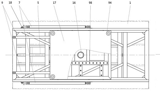
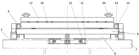
[0002] Barrier vehicles are mainly used to block, block and deter riots and riots, set up roadblocks, and achieve the purposes of dispersing violent
crowds, target protection, area prevention, and on-site control. The existing barrier vehicles have a low degree of
automation. The loading and unloading of the blocking wall is manually operated, the work intensity is high, and the deployment and removal time is long, which greatly affects the efficiency of handling emergencies. After retrieval,
Chinese patent CN212958056U discloses a
fully automatic intelligent blocking wall system barrier vehicle. It is characterized in that it is provided with a vehicle
cockpit, a vehicle chassis, an automatic unloading platform, and a modular blocking wall system. The automatic unloading platform is provided with a rail frame, a rotating device, and a hydraulic module. The rail frame is provided with rails and cross bars. , the track is provided with a horizontal portion and a vertical portion, the horizontal portion is installed on the upper surface of the vehicle chassis, the vertical portion is disposed outside the rear side of the vehicle chassis, the vertical portion faces the ground, the The rotating device is provided with a plane rotating unit, a side wall roller, and a front wall hinge hole. The center of the top surface of the plane rotating unit is provided with a rotating shaft, the side wall roller is arranged in the track, and the side wall The roller slides along the track, the hydraulic module is arranged inside the rail frame, the hydraulic module is provided with an output rod, and the front end of the output rod of the hydraulic module is hingedly connected with the hinge hole of the front wall of the rotating device, The modular blocking wall system is provided with a first blocking wall and a second blocking wall, the bottom surface of the first blocking wall is installed on the rotating shaft of the plane rotation unit, and the second blocking wall is provided with a plurality of , the sides of the first blocking wall are connected to the adjacent second blocking walls, and the two sides of the adjacent second blocking walls are connected to each other, and the above-mentioned side connecting positions are all set There is a
servo motor planetary reduction power shaft module. There are two rails, which are respectively arranged on the left and right sides of the rail frame. The two rails are C-shaped cross-section rails, and the C-shaped cross-section rails are provided with side gaps. The side gaps of the left and right two C-shaped cross-section rails face the inner side of the rail frame horizontally and facing the ground, and the side wall rollers are arranged on the left and right side walls of the plane rotating unit, and the plane rotating unit Two side wall rollers are respectively arranged on the left and right side walls of the unit. The side wall rollers are arranged in the C-shaped section track, and the side wall rollers move along the C-shaped section track. The crossbar is connected between the two rails and is located at the bottom of the rail frame. The hydraulic module is arranged inside the rail frame and installed on the crossbar. The hydraulic module is arranged on the rail frame close to the
cockpit of the vehicle The end of the first blocking wall is installed on the rotating shaft, and the center of symmetry of the first blocking wall is located on the axis of the rotating shaft, and the left and right sides of the first blocking wall Second blocking walls are respectively provided, the number of second blocking walls on the left and right sides of the first blocking wall is equal, the height of the first blocking wall is equal to the height of the second blocking wall, and the first blocking wall The width of a blocking wall is twice the width of the second blocking wall, driven by the planetary reduction power shaft module of the
servo motor, the first blocking wall and the second blocking wall connected side by side The included angle between the retaining walls can be changed, the first
retaining wall and the second
retaining wall are provided with bottom edges, and the bottom edges are all equipped with universal wheels. The deficiencies of the above-mentioned patents: one is that The patent uses the horizontal part and vertical part of the track to load and unload the blocking wall system. The blocking wall system is set on the rotating shaft of the rotating device, and the hinge hole of the front wall of the rotating device is hinged with the output rod of the hydraulic module, which pushes the blocking wall through the output rod of the hydraulic module. The wall system moves horizontally and vertically up and down, combined with the attached Figure 9 , we can see that the rotating device cannot be bent, so the blocking wall system cannot move down smoothly after moving horizontally to the rear of the vehicle, the blocking wall system may not be able to be deployed vertically, and the height of the blocking net is limited. The speed is slow, and it may not be blocked in time; the second is that the ground where the barrier vehicle is set is often uneven or has a large slope, and the universal wheels of the above patent cannot adapt to it. The blocking effect is weak; the third is the lack of a limit fixing device between the blocking wall system and the vehicle chassis in the above patent, which makes the blocking wall system easy to shake when the vehicle is moving, and the blocking wall system may slide when the
road surface is uneven or has a slope , not only the hydraulic module will be damaged, but the blocking wall system may also come out of the vehicle chassis, causing traffic accidents; Fourth, the angle of the first blocking wall and the second blocking wall in the above blocking wall system cannot be adjusted, and the place of use is limited


