
Main speed reducer bearing unit and assembling method

A main reducer and bearing technology, which is applied in the field of final reducer bearing units and assembly, and can solve problems such as difficult to accurately preload

Pending Publication Date: 2021-09-10
山东朝阳轴承有限公司
View PDF8 Cites 0 Cited by
  • Summary
  • Abstract
  • Description
  • Claims
  • Application Information

AI Technical Summary

Problems solved by technology

[0004] Aiming at the deficiencies and defects in the prior art, the present invention provides a bearing unit and an assembly method of the main reducer, which are used to solve the problem in the prior art that it is difficult to achieve accurate preload when using gaskets to adjust the distance between the inner rings of the bearings

Method used


Image

  • Main speed reducer bearing unit and assembling method
  • Main speed reducer bearing unit and assembling method
  • Main speed reducer bearing unit and assembling method

Examples


Embodiment Construction

[0048] Embodiments of the present invention are described below through specific examples, and those skilled in the art can easily understand other advantages and effects of the present invention from the content disclosed in this specification. The present invention can also be implemented or applied through other different specific embodiments. At the same time, terms such as "upper", "lower", "left", "right", "middle" and "one" quoted in this specification The terminology is only used for clarity of description, and is not used to limit the applicable scope of the present invention. Changes or adjustments of their relative relationships shall also be regarded as the applicable scope of the present invention without substantive changes in the technical content.

[0049] It should be noted that the diagrams provided in this embodiment are only schematically illustrating the basic concept of the present invention, although only the components related to the present invention ar...


PUM


Abstract

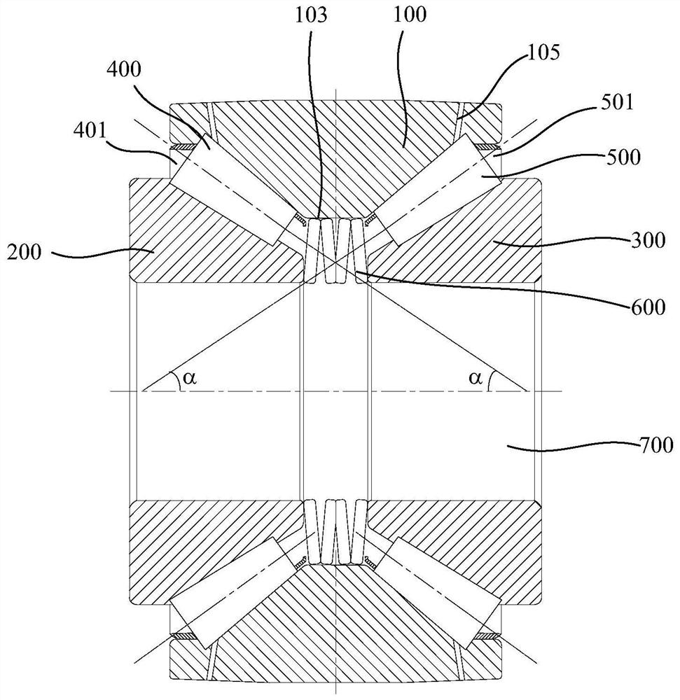
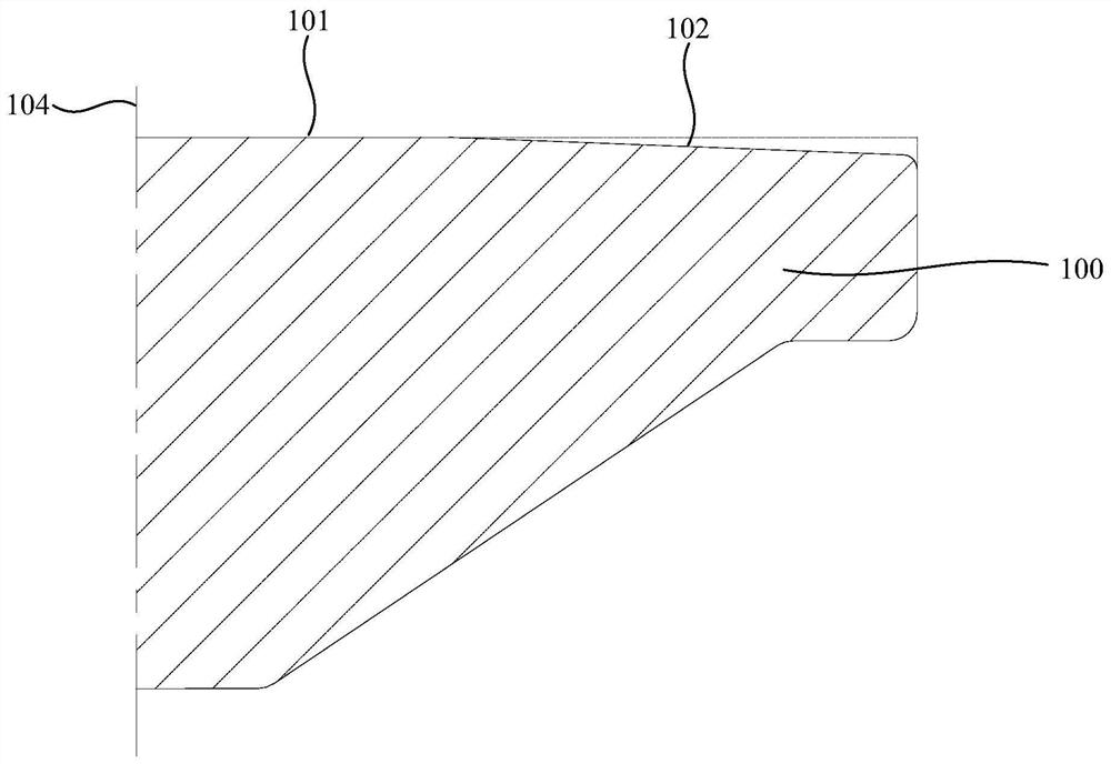
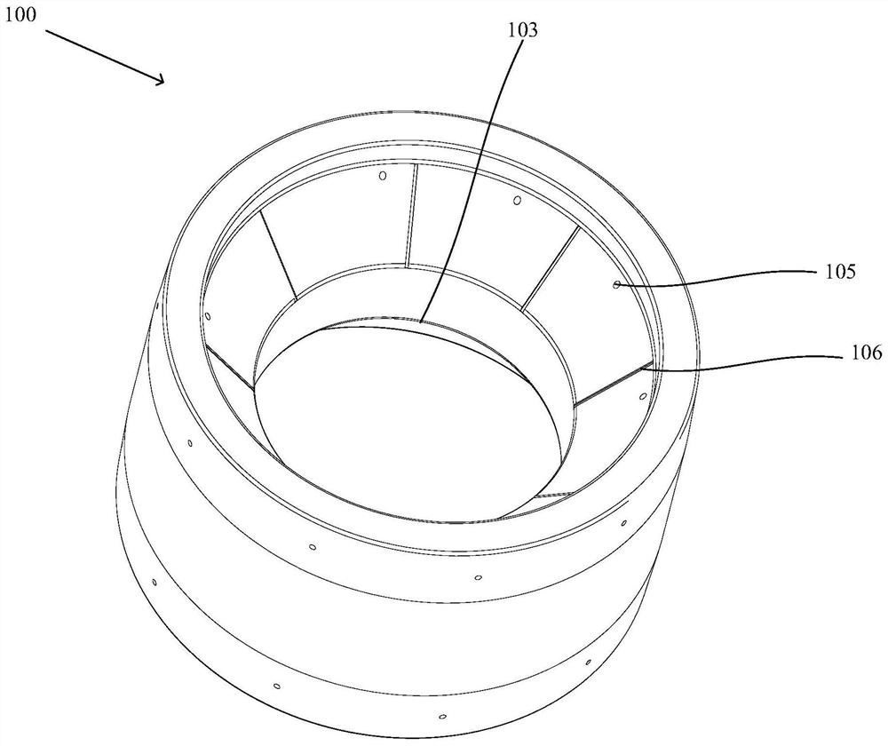
The invention provides a main speed reducer bearing unit and an assembling method. The main speed reducer bearing unit comprises a bearing outer ring, a first bearing inner ring, a second bearing inner ring, first tapered rollers, second tapered rollers and elastic bodies. The bearing outer ring is mounted on a bearing seat of a main speed reducer; the first bearing inner ring is coaxially and rotatably mounted at the inner side of the bearing outer ring, and the first bearing inner ring and the bearing outer ring form a first tapered roller path; the second bearing inner ring is coaxially and rotatably mounted at the inner side of the bearing outer ring, and the second bearing inner ring and the bearing outer ring form a second tapered roller path; the first tapered rollers are mounted in the first tapered roller path; the second tapered rollers are mounted in the second tapered roller path; and the elastic bodies are installed between the first bearing inner ring and the second bearing inner ring. The main speed reducer bearing unit is simple in structure, and solves the problem that accurate axial pre-tightening is not prone to be realized when a gasket is adopted to adjust the distance between the the bearing inner rings in the prior art.

Description

technical field [0001] The invention relates to the technical field of the main reducer of an automobile drive axle, in particular to a bearing unit and an assembly method of the main reducer. Background technique [0002] In the design and maintenance of the vehicle, the drive axle is one of the important components of the car, and the tapered roller bearing is the key part of the main reducer of the car drive axle. When the main reducer of the drive axle is working, the tapered roller bearing bears a large axial load and a high speed, which often causes the rolling bearing to slip, skew, and violent friction between the rolling body and the raceway, resulting in ablation of the rolling body Even bearings fail prematurely. [0003] At present, the commonly used main reducer bearings are ordinary tapered roller bearings. Since the contact angle of ordinary tapered roller bearings is less than 30°, it is difficult to withstand large axial loads for a long time, resulting in ...

Claims


Application Information

Patent Timeline
Patent Type & Authority Applications(China)
IPC IPC(8): F16C25/08F16C33/58F16C33/64F16C33/66F16C43/06F16H57/022
CPCF16C25/083F16C33/6681F16C33/6651F16C33/583F16C33/64F16C43/065F16H57/022F16C2223/08F16C2361/65
Inventor 唐元超李畅万心海郭祥飞靳祖孟吴勃刘文君
Owner 山东朝阳轴承有限公司
Learn More