A self-locking air duct hanger

A self-locking, air duct technology, applied in the direction of pipe supports, pipes/pipe joints/fittings, mechanical equipment, etc., can solve problems such as high safety risks, achieve the effects of reducing safety hazards, convenient operation, and improving work efficiency

Active Publication Date: 2022-06-28
JIANGSU TIANLI CONSTR GRP
View PDF10 Cites 0 Cited by
  • Summary
  • Abstract
  • Description
  • Claims
  • Application Information

AI Technical Summary

Problems solved by technology

[0006] In order to improve the problem that construction workers need to climb up to pull out the T-shaped self-locking components, there is a big safety risk. This application provides a self-locking air duct hanger

Method used


Image

  • A self-locking air duct hanger
  • A self-locking air duct hanger
  • A self-locking air duct hanger

Examples


Embodiment 1

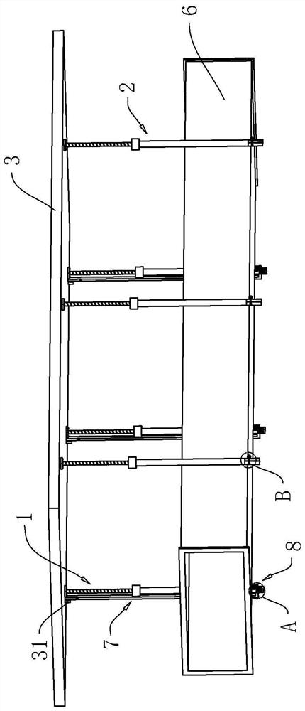
[0036] The embodiment of the present application discloses a self-locking air duct hanger. refer to figure 1 as well as figure 2 , a self-locking air duct hanger includes a plurality of first hanger rods 1 and second hanger rods 2, the first hanger rods 1 and the second hanger rods 2 are both vertically arranged and parallel to each other. Both ends of the first suspension rod 1 and the second suspension rod 2 away from the ground are fixed to the floor plate 3 . A waist-shaped groove 4 is defined at one end of the first hanging rod 1 away from the floor 3 , and the waist-shaped groove 4 is arranged along the length direction of the first hanging rod 1 . The waist-shaped groove 4 is provided with a rotating shaft 5, and a support rod 7 is rotated on the rotating shaft 5, and the support rod 7 is used to support the air duct body 6 to reduce the risk of the air duct body 6 falling off. A baffle 31 is installed on the floor 3 , and one end side of the support rod 7 away from...

Embodiment 2

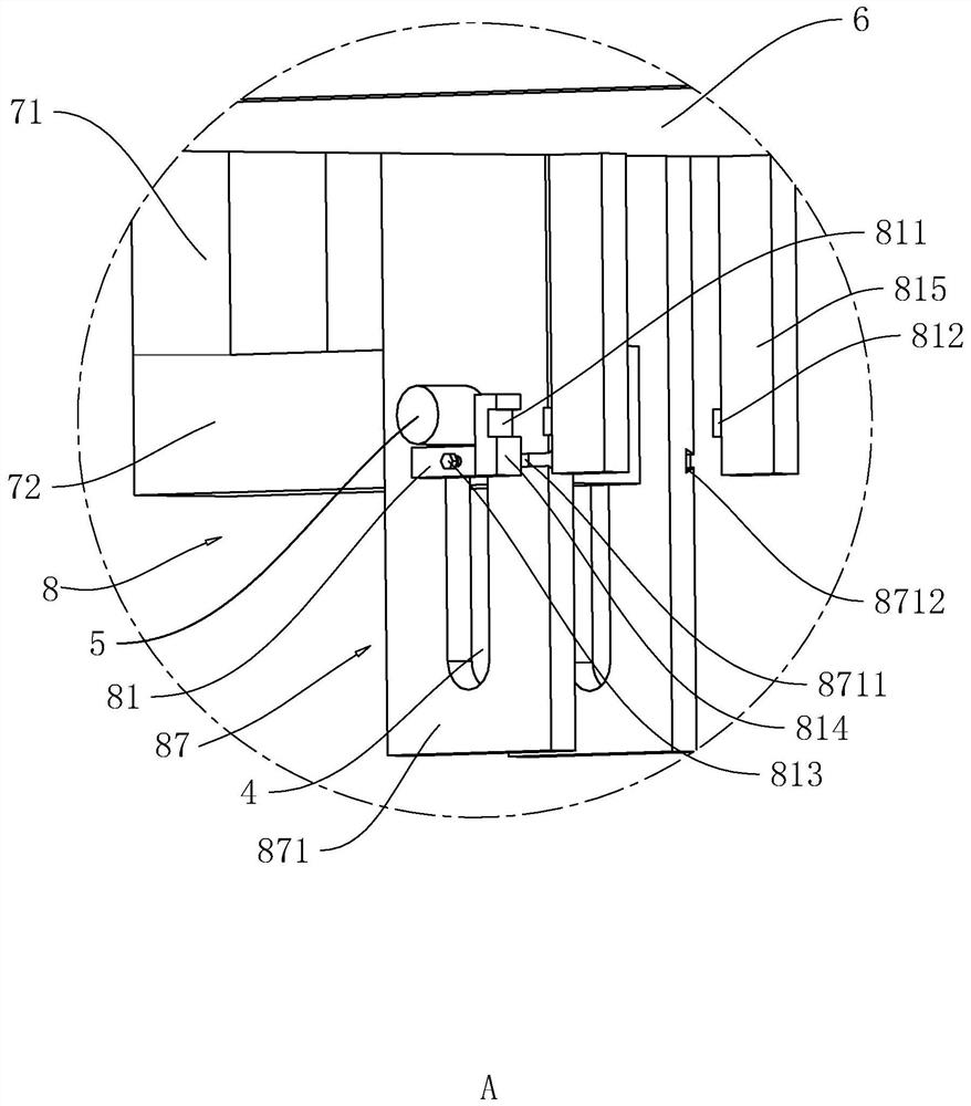
[0048] The embodiment of the present application discloses a self-locking air duct hanger. The difference from Example 1 is: refer to Figure 5 , the adjustment assembly 8 includes a drive shaft 85 rotatably connected with the vertical plate 871 , and the rotation axis of the drive shaft 85 is parallel to the rotation axis of the rotation shaft 5 . A gear 83 is coaxially sleeved on the drive shaft 85, and the gear 83 and the drive shaft 85 are connected and fixed by a key. The side wall of the vertical plate 871 is provided with a sliding groove 8713 , and the sliding groove 8713 is arranged along the vertical direction of the vertical plate 871 . A bump is welded on one side, the bump is slidably connected with the sliding groove 8713 , and the rack 84 meshes with the gear 83 . A slider 82 is welded on the rack 84 , and the side of the slider 82 away from the ground is in contact with the side surface of the rotating shaft 5 . The rotation of the rotating shaft 5 drives th...


PUM


Abstract

This application relates to a self-locking air duct hanger, which relates to the technical field of building construction, and includes several first hangers and second hangers, both of which are fixedly connected to the floor. The end of the first suspender away from the floor is provided with a waist-shaped groove, and a rotating shaft is arranged in the waist-shaped groove, and a supporting rod for supporting the air duct body is connected to the rotating shaft, and a baffle is fixedly connected to the floor , the baffle abuts against the end of the supporting rod away from the rotating shaft, and the first suspender is provided with an adjusting assembly for adjusting the height of the rotating shaft. The adjustment component drives the rotating shaft to slide down along the length of the waist-shaped groove, so that the end of the supporting rod away from the rotating shaft is separated from the baffle plate. Under the action of gravity, the supporting rod rotates 180° around the rotating shaft and then hangs vertically. The board is detached, which is convenient to operate and reduces potential safety hazards.

Description

technical field [0001] The present application relates to the technical field of building construction, in particular to a self-locking air duct hanger. Background technique [0002] At present, with the continuous improvement of people's living standards, the system functions of large-scale projects are also becoming more and more perfect, and the types and numbers of mechanical and electrical equipment pipelines have increased. During the construction of the underground garage, in order not to affect the normal passage of vehicles, the underground garage has higher requirements on the clearance height. Therefore, when installing the air system pipeline, it is necessary to design the air duct hanger separately to meet the requirements. [0003] The Chinese patent with the publication number CN106764048B discloses a method for installing an air duct by using a self-locking air duct hanger, including the steps of designing the air duct hanger: the air duct hanger includes a f...

Claims


Application Information

Patent Timeline
Patent Type & Authority Patents(China)
IPC IPC(8): F16L3/02
CPCF16L3/006F16L3/02
Inventor 潘晓杰崔晓均杨晓周建平
Owner JIANGSU TIANLI CONSTR GRP
Why Eureka
Try Eureka