
Interactive image projection equipment and use method thereof

A technology of projection equipment and interactive images, applied in mechanical equipment, instruments, machines/stands, etc., can solve problems such as damage to interactive image projection equipment, affecting the normal use of projection equipment, and affecting the disassembly efficiency of maintenance personnel.

Pending Publication Date: 2021-09-10
JINLING INST OF TECH
View PDF11 Cites 0 Cited by
  • Summary
  • Abstract
  • Description
  • Claims
  • Application Information

AI Technical Summary

Problems solved by technology

[0004] 1. After using the interactive image projection equipment for a long time, it will cause damage to the interactive image projection equipment. Because the projection equipment used in the classroom is generally installed on the top of the room, but the current projection equipment is not easy to disassemble. , which will affect the disassembly efficiency of maintenance personnel;
[0005] 2. When using interactive video equipment, the stability of the existing video equipment is insufficient, which will affect the normal use of the projection equipment;
[0006] 3. Since the current projection equipment is directly fixed on the top of the room, and the angle adjustment function cannot be performed, when the angle of the projection equipment is misaligned, when the projection equipment is used, the projected image will appear abnormal.

Method used


Image

  • Interactive image projection equipment and use method thereof
  • Interactive image projection equipment and use method thereof
  • Interactive image projection equipment and use method thereof

Examples


Embodiment Construction

[0041] The following will clearly and completely describe the technical solutions in the embodiments of the present invention with reference to the drawings in the embodiments of the present invention.

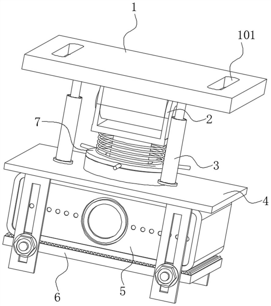
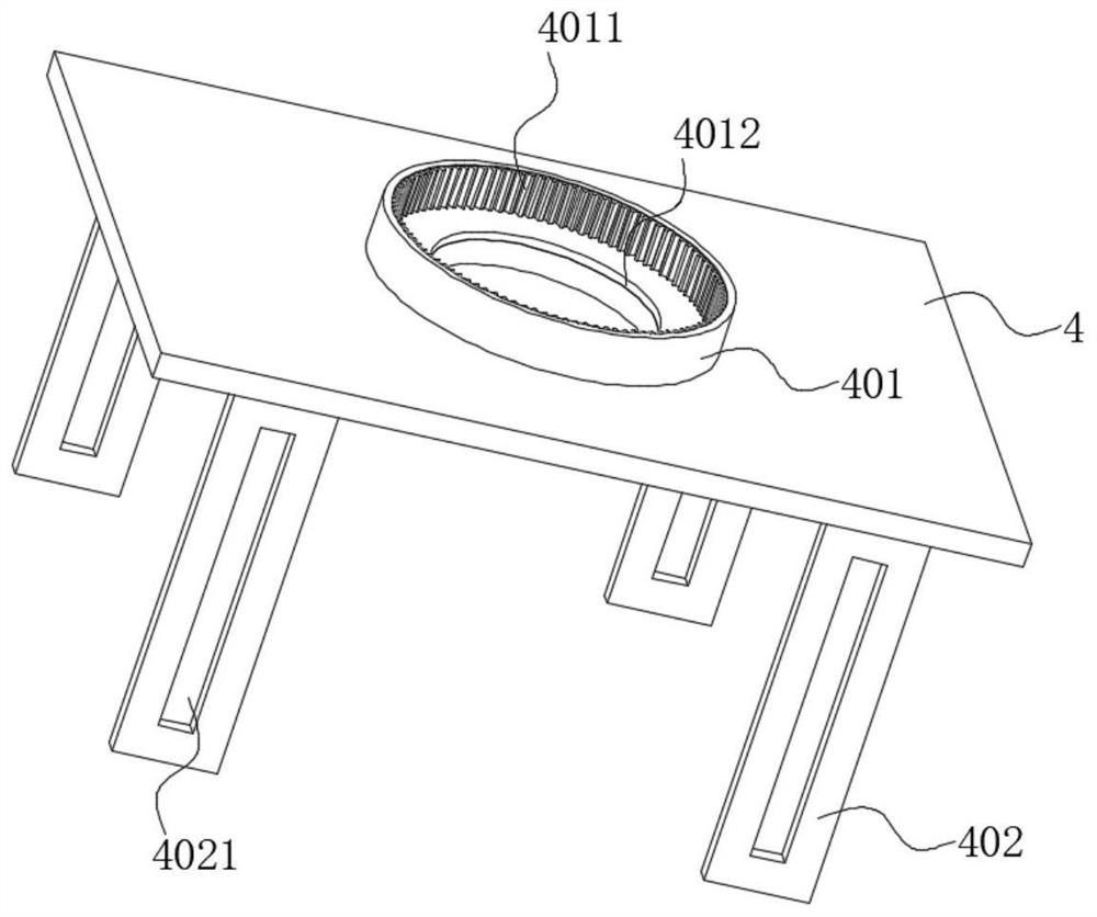
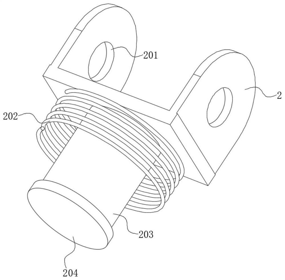
[0042] see Figure 1-8 As shown, the present invention is a device for interactive image projection, including a projector 5, the upper end of the projector 5 is provided with a connecting plate 4, the middle position of the lower side of the connecting plate 4 is fixed with a friction plate 404, and the bottom of the projector 5 A bottom plate 6 is arranged on the side, and a friction pad 601 is fixed in the middle of the upper side of the bottom plate 6. Locking screws 603 are fixed on the left and right sides of the front and rear sides of the bottom plate 6, and the positions corresponding to the locking screw 603 are fixed on the lower side of the connecting plate 4 There is an adjustment frame 402, and the side walls of the adjustment frame 402 are provided with adjustme...


PUM


Abstract

The invention discloses interactive image projection equipment and a use method thereof, and relates to the technical field of teaching auxiliary related equipment. The interactive image projection equipment comprises a projector, a connecting plate is arranged at the upper end of the projector, a friction plate is fixed to the middle of the lower side of the connecting plate, a bottom plate is arranged on the lower side of the projector, a friction pad is fixed to the middle of the upper side of the bottom plate, and locking screws are fixed to the left and right portions of the front and rear sides of the bottom plate. Adjusting frames are fixed to the positions, corresponding to the locking screws, of the lower side of the connecting plate, a containing cylinder is fixed to the middle of the upper side of the connecting plate, a gear groove is formed in the containing cylinder, a containing ring is arranged at the upper end of the containing cylinder, and an outer gear ring is fixed to the middle of the lower side of the containing ring. According to the interactive image projection equipment, the locking screws move downwards on the adjusting frames, and the projector is convenient to disassemble; when the friction plate and the friction pad extrude the projector, large friction is generated on the upper end and the lower end of the projector, and the stability of the projector is improved; and the outer gear ring is moved out of the gear ring groove, and the angle of the projector is convenient to adjust.

Description

technical field [0001] The invention belongs to the technical field of teaching aid related equipment, and in particular relates to an interactive image projection equipment and a using method thereof. Background technique [0002] A projector, also known as a projector, is a device that can project images or videos onto a screen. It can be connected to a computer, VCD, DVD, BD, game console, DV, etc. through different interfaces to play the corresponding video signal. In schools, in order to improve the teaching of students, interactive projection equipment will be installed in classrooms. [0003] Existing public document, CN210462295U-a kind of multimedia interactive projection equipment, belongs to the field of projection equipment. Including: each arc-shaped limiting plate is provided with an arc-shaped long hole, the tail of the main body of the projection equipment is hinged to the lower end surface of the base, a driving electric cylinder is arranged between the upp...

Claims


Application Information

Patent Timeline
IPC IPC(8): F16M11/04F16M11/12F16M11/16F16M11/18F16M13/02G03B21/54
CPCF16M11/04F16M11/121F16M11/16F16M11/18F16M13/027G03B21/54Y02D10/00
Inventor 齐建明
Owner JINLING INST OF TECH
Learn More