Optical fiber clamp and fusion splicer

A technology of optical fiber fusion splicer and optical fiber joint, which is applied in the direction of light guide, optics, optical components, etc., and can solve the problems of affecting welding effect, optical fiber position, and inability to clamp.

Pending Publication Date: 2021-09-10
中电科思仪科技(安徽)有限公司
View PDF0 Cites 1 Cited by
  • Summary
  • Abstract
  • Description
  • Claims
  • Application Information

AI Technical Summary

Problems solved by technology

For optical fibers with special connectors, the existing optical fiber clamps cannot clamp them tightly, and it is easy to affect the position of the optical fibers during the clamping process, affecting the subsequent welding effect

Method used


Image

  • Optical fiber clamp and fusion splicer
  • Optical fiber clamp and fusion splicer
  • Optical fiber clamp and fusion splicer

Examples


Embodiment 1

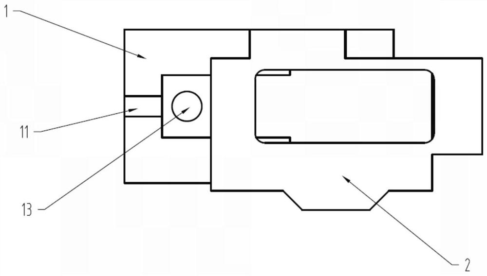
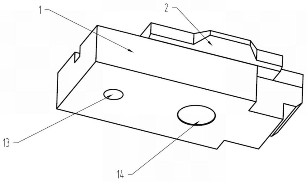
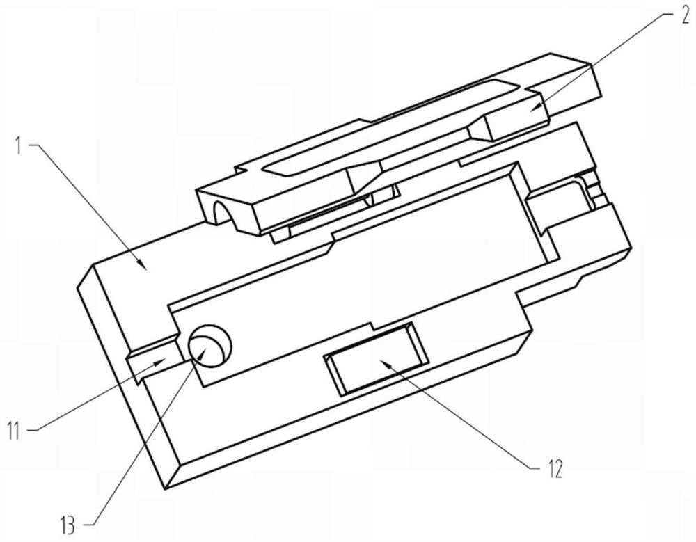
[0026] Such as Figures 1 to 4 As shown, the optical fiber clamp of the present invention includes a clamp base 1 and a platen cover 2, which are hinged to each other.

[0027] The fixture base 1 is roughly in the shape of a cuboid, and the fixture base 1 is made of metal. The upper end surface of the fixture base 1 is near the middle position and has an optical fiber groove 11 that runs through its vertical two sides. The outer contour of the fixture base 1 is embedded with a first magnet 12 at the right and front positions of the upper end surface of the fixture base 1, and the first magnet 12 can be attracted to the pressure plate cover 2;

[0028] The fixture base 1 is provided with a circular limit hole 13 that matches the limit pin of the base of the optical fiber fusion splicer. A second magnet 14 that can be attracted to the base of the optical fiber fusion splicer is embedded in the lower end surface of the fixture base 1 .

[0029] Both the first magnet 12 and the ...

Embodiment 2

[0033] During installation, the optical fiber clamp of the present invention is placed on the base of the optical fiber fusion splicer. The limit hole 13 of the fixture base 1 cooperates with the limit pin of the base of the optical fiber fusion splicer, and at the same time, the second magnet 14 of the fixture base 1 is integrally attracted to the base of the optical fiber fusion splicer to complete the installation of the optical fiber fixture; before welding, Insert the special connector fiber into the fiber groove 11, and then cover the platen cover 2. The outer contour of the special connector fiber fits perfectly with the special-shaped hole of the fiber groove 11 and the pressure plate cover 2, thereby clamping it, and finally completing the positioning of the fiber.

[0034] Such as Figure 5 One of the optical fibers with a special connector is displayed, which is an SC connector. Before fusion splicing, the optical fiber is inserted between the fiber groove 11 and th...


PUM


Abstract

The invention discloses an optical fiber clamp and a fusion splicer, and belongs to the field of optical fiber fusion splicers. The optical fiber clamp comprises a pressing plate cover and a base, the pressing plate cover is hinged to the base, the upper end face of the base is provided with an optical fiber groove penetrating through the end faces of the two sides of the base, the middle of the pressing plate cover is provided with a special-shaped hole suitable for a special optical fiber connector, and the pressing plate cover covers the upper side of the optical fiber groove of the base; a magnet capable of being attracted with the pressing plate cover is embedded in the position, corresponding to the pressing plate cover, of the upper end face of the base, and a limiting hole is further formed in one side of the base; and the optical fiber clamp is installed on the base of the optical fiber fusion splicer, the second magnet of the clamp base is integrally attracted to the base of the optical fiber fusion splicer, and the limiting hole of the clamp base is matched with the limiting pin of the base of the optical fiber fusion splicer. The requirement for reliable positioning of the special connector optical fiber is met, the optical fiber can enter the groove quickly, and it is guaranteed that the optical fiber is not dislocated.

Description

technical field [0001] The invention belongs to the field of optical fiber fusion splicers, and in particular relates to an optical fiber clamp and a fusion splicer. Background technique [0002] Optical fiber fusion splicers are mainly used for the construction and maintenance of optical cables in optical communications. The general working principle is to use a high-voltage arc to melt the end faces of the two optical fibers, and at the same time use a high-precision motion mechanism to gently advance the two optical fibers into one, so as to realize the coupling of the optical fiber mode field. Before fusion splicing, the optical fiber needs to be clamped by the optical fiber clamp. In order to ensure the accurate docking of the two optical fiber end faces, the optical fiber clamp must be able to clamp the optical fiber stably to avoid the deviation of the optical fiber during the docking. For optical fibers with special connectors, the existing optical fiber clamps cann...

Claims


Application Information

Patent Timeline
Patent Type & Authority Applications(China)
IPC IPC(8): G02B6/255
CPCG02B6/2553G02B6/2555
Inventor 王鹏彭杰包明帝陈川李博贺永亮任晓楠
Owner 中电科思仪科技(安徽)有限公司
Why Eureka
Try Eureka