Lens design method

A design method and lens technology, applied in optical components, optics, instruments, etc., can solve problems such as difficult imaging of lenses, large deformation of plastic lenses, and abnormal imaging of lens systems

Active Publication Date: 2021-09-10
JIAXING ZHONGRUN OPTICAL TECH
View PDF12 Cites 0 Cited by
  • Summary
  • Abstract
  • Description
  • Claims
  • Application Information

AI Technical Summary

Problems solved by technology

[0002] At present, the plastic lens in the wave-plastic hybrid lens designed and produced in the market has the problem of temperature drift at high temperature, which is mainly manifested in the large deformation or even irreversible deformation of the plastic lens at high temperature, which leads to the failure of the entire lens system to image normally, which leads to production failure. fail
[0003] This problem is mainly caused by the Image 6 As shown, the abutment lens is directly assembled into the lens barrel, and it is usually subjected to axial force along the optical axis and radial force. The former mainly comes from the locking force of the pressure ring, the pressure of expansion or contraction in the front and rear directions, and the latter mainly comes from the temperature. After the change, the pressure of the outer diameter of the abutment lens and the lens barrel, and the abutment lens itself is asymmetrical both in the radial direction and in the axial direction, resulting in a large deformation of the abutment lens, making it difficult for the lens to image, reducing the Image quality of the lens

Method used


Image

  • Lens design method
  • Lens design method
  • Lens design method

Examples


Embodiment 1

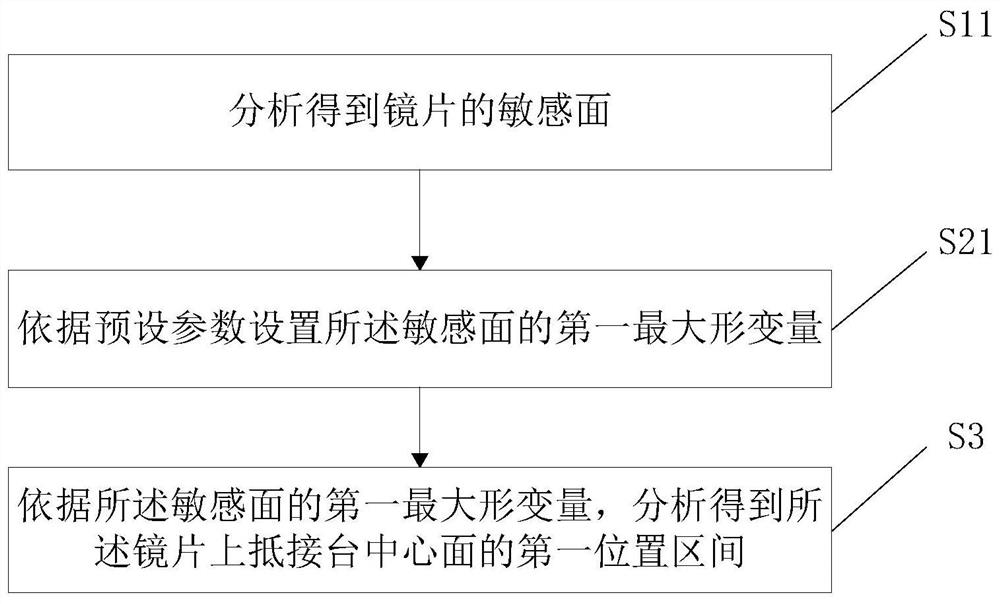
[0094] Such as figure 1 , Figure 7 with Figure 8 Shown, a kind of lens design method comprises the following steps:

[0095] S11. Analyzing and obtaining the sensitive surface of the lens.

[0096] First calculate the curved surfaces on both sides of the lens, which of the two curved surfaces is more sensitive, and use the more sensitive curved surface as the sensitive surface.

[0097] S21. Set the first maximum deformation amount of the sensitive surface according to preset parameters.

[0098] According to the installation of the first lens L1 to the sixth lens L6 in the lens barrel 1, the focal length, focal power, image height, aberration and other related parameters of the lens are used as preset parameters to limit the deformation of the lens, and then The first maximum deformation of the sensitive surface is formed. Therefore, the lens can only meet the relevant parameter requirements when the deformation of the sensitive surface is less than or equal to the fir...

Embodiment 2

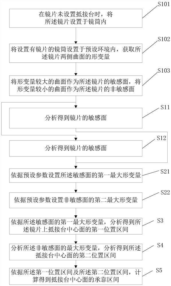
[0103] Such as figure 1 , figure 2 with Figure 8 Shown, a kind of lens design method comprises the following steps:

[0104] S101 . When the lens is not provided with an abutment platform, place the lens in the lens barrel 1 .

[0105] In the current state, if the lens is directly placed in the lens barrel 1, the lens will be deformed after abnormal temperature.

[0106] S102. Set the lens barrel 1 provided with the lenses in a preset environment, and obtain the deformation of the curved surfaces on both sides of the lenses.

[0107] The preset environment can be changed according to the user's settings. Specifically, the preset environment mainly refers to different temperature environments. After a period of time, the lens will be deformed, and the user can measure the deformation on both sides of the lens.

[0108] S103. Use a curved surface with a larger deformation amount as a sensitive surface of the lens, and use a curved surface with a smaller deformation amount...

Embodiment 3

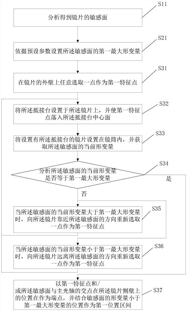
[0120] Such as image 3 , Figure 7 with Figure 8 Shown, a kind of lens design method comprises the following steps:

[0121] S11. Analyzing and obtaining the sensitive surface of the lens.

[0122] S21. Set the first maximum deformation amount of the sensitive surface according to preset parameters.

[0123] S31. Randomly select a point on the outer wall of the lens as the first feature point.

[0124] S32. Set the abutment platform on the lens, and make the first feature point fall into the central plane of the abutment platform;

[0125] S33. Set the lens provided with the abutting platform in the lens barrel 1, and acquire the current deformation of the sensitive surface.

[0126] After the abutment platform is set on the first feature point, the abutment platform is located at the end close to the sensitive surface, and in the current state, the lens is placed in the lens barrel 1 again, and the current deformation of the sensitive surface is obtained. At this time ...


PUM


Abstract

The invention relates to the field of optical devices, in particular to a lens design method which comprises the following steps: S11, analyzing to obtain a sensitive surface of a lens; s21, setting a first maximum deformation quantity of the sensitive surface according to a preset parameter; and S3, analyzing to obtain a first position interval of the central surface of the abutting table on the lens according to the first maximum deformation quantity of the sensitive surface. Through the setting of the steps, the pressure in the radial direction of the lens is reduced, then the possibility of deformation is reduced, the possibility that the lens is difficult to image is reduced, and the imaging quality of the lens is improved.

Description

technical field [0001] The invention relates to the field of optical devices, in particular to a lens design method. Background technique [0002] At present, the plastic lens in the wave-plastic hybrid lens designed and produced in the market has the problem of temperature drift at high temperature, which is mainly manifested in the large deformation or even irreversible deformation of the plastic lens at high temperature, which leads to the failure of the entire lens system to image normally, which leads to production failure. fail. [0003] This problem is mainly caused by the Image 6 As shown, the abutment lens is directly assembled into the lens barrel, and it is usually subjected to axial force along the optical axis and radial force. The former mainly comes from the locking force of the pressure ring, the pressure of expansion or contraction in the front and rear directions, and the latter mainly comes from the temperature. After the change, the pressure of the oute...

Claims


Application Information

Patent Timeline
Patent Type & Authority Applications(China)
IPC IPC(8): G02B27/00
CPCG02B27/0012
Inventor 何宇向诗文罗积来傅玉宏陈三忠
Owner JIAXING ZHONGRUN OPTICAL TECH
Why Eureka
Try Eureka