
Miniaturized polarization point diffraction digital holographic microscopy device based on LED illumination

A technology of digital holographic microscopy and LED lighting, applied in the direction of instruments, etc., can solve the problems of reduced sensitivity and accuracy, inability to guarantee accuracy, and inability to guarantee the contrast of interference fringes

Active Publication Date: 2021-09-10
XIDIAN UNIV
View PDF4 Cites 1 Cited by
  • Summary
  • Abstract
  • Description
  • Claims
  • Application Information

AI Technical Summary

Problems solved by technology

It should be noted that the reference light in this technique is generated by filtering the object light wave, so the light intensity of the reference light is directly related to the scattering degree of the measured sample, and there is no guarantee that the interference fringes will have a good appearance under any sample. contrast, the accuracy of the reconstruction cannot be guaranteed
In addition, the traditional digital holographic microscopy technology uses highly coherent laser light for illumination, and can obtain a high-contrast hologram. However, the high coherence causes the image to have serious speckle noise, which reduces the sensitivity and accuracy of the measurement.

Method used


Image

  • Miniaturized polarization point diffraction digital holographic microscopy device based on LED illumination
  • Miniaturized polarization point diffraction digital holographic microscopy device based on LED illumination
  • Miniaturized polarization point diffraction digital holographic microscopy device based on LED illumination

Examples


Embodiment Construction

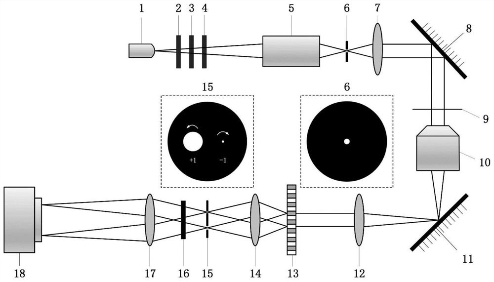
[0035] In order to further explain the technical means and effects of the present invention to achieve the intended purpose of the invention, the miniaturized polarization point diffraction digital holographic microscope device based on LED lighting proposed according to the present invention will be described in detail below in conjunction with the accompanying drawings and specific implementation methods .

[0036]The aforementioned and other technical contents, features and effects of the present invention can be clearly presented in the following detailed description of specific implementations with accompanying drawings. Through the description of specific embodiments, the technical means and effects of the present invention to achieve the intended purpose can be understood more deeply and specifically, but the accompanying drawings are only for reference and description, and are not used to explain the technical aspects of the present invention. program is limited.

[0...


PUM

PropertyMeasurementUnit
Diameteraaaaaaaaaa

Abstract

The invention discloses a miniaturized polarization point diffraction digital holographic microscopy device based on LED illumination. The device comprises a partially coherent light generation and regulation module, a light size control module, a telescope system, an object light and reference light separation module and an image acquisition module which are sequentially arranged along the direction of a light path, wherein the partially coherent light generation and regulation module is used for generating partially coherent light and regulating the polarization characteristic of the partially coherent light, the light size control module is used for scaling the size of the polarized light and generating uniform illumination light waves, the telescope system is used for amplifying and imaging a sample to form light field distribution with sample information, the object light and reference light separation module is used for diffracting the light with the sample information to generate object light and reference light, and the image acquisition module is used for acquiring a hologram generated by the object light and the reference light. According to the invention, the object light and the reference light pass through the identical optical elements, so that the system has very good immunity to environmental disturbance, and the low-coherence LED is adopted for illumination, so that the image quality is greatly improved.

Description

technical field [0001] The invention belongs to the technical field of optical microscopic imaging, and in particular relates to a miniaturized polarization point diffraction digital holographic microscopic device based on LED lighting, which is used for in-situ detection of transparent samples without marking, with high contrast and high resolution. Background technique [0002] In current biological research and medical diagnosis, single cells or biological tissues are the main objects that reflect the life state of organisms. Electron microscopes and atomic force microscopes have nanometer or even sub-nanometer spatial resolution, and can detect the fine structures of various subcellular organelles, providing reliable detection methods and important scientific basis for the diagnosis and treatment of many diseases. Since these techniques have special requirements for sample preparation and have certain physical or chemical damage to the sample during the detection process...

Claims


Application Information

Patent Timeline
IPC IPC(8): G03H1/00G03H1/04
CPCG03H1/0005G03H1/0443G03H1/0465G03H2001/0038G03H2001/005
Inventor 马英卓可群王宇郜鹏郑娟娟马琳刘旻
Owner XIDIAN UNIV
Learn More