
Multi-path position comparison output device based on FPGA

A technology for outputting device and position value, applied in the field of measurement and control, can solve the problem of high cost, achieve the effects of ensuring stability, ensuring high-speed and orderly control, and reducing storage resource consumption

Pending Publication Date: 2021-09-10
GUANGDONG SAMSUN TECH CO LTD
View PDF0 Cites 0 Cited by
  • Summary
  • Abstract
  • Description
  • Claims
  • Application Information

AI Technical Summary

Problems solved by technology

However, the products that can complete the position comparison function in the current market all rely on the motion control card, which has the problem of high cost, and the motion control card often only provides single-way position comparison, which cannot meet the current needs of multi-way comparison.

Method used


Image

  • Multi-path position comparison output device based on FPGA
  • Multi-path position comparison output device based on FPGA
  • Multi-path position comparison output device based on FPGA

Examples


Embodiment Construction

[0041] The present invention will be further described below in conjunction with accompanying drawing:

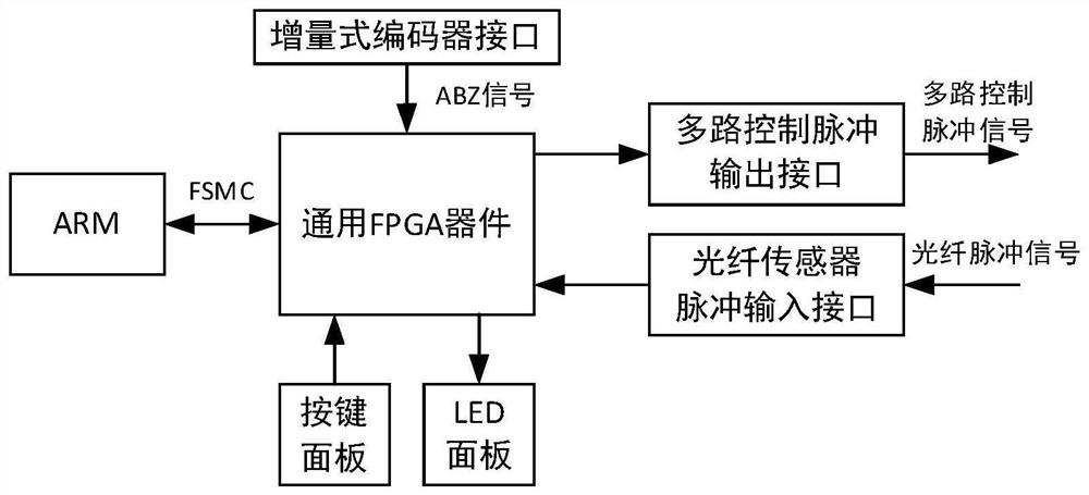
[0042] as attached figure 1 As shown, the present invention is made up of button operation panel, LED display panel, general ARM controller and general FPGA device, and described general FPGA device is provided with fiber optic sensor pulse input interface, multi-channel control pulse output interface and incremental encoder Interface, the general-purpose FPGA device is connected with the general-purpose ARM controller through the FSMC parallel bus interface, the control input end of the described general-purpose FPGA device is connected with the described button operation panel, and the display signal output end of the described general-purpose FPGA device is connected with the described general-purpose FPGA device. LED panel connections described above.

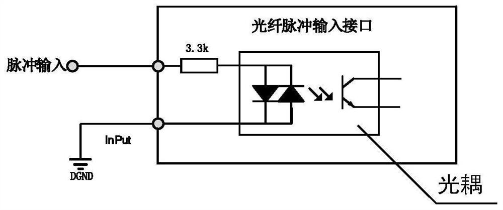
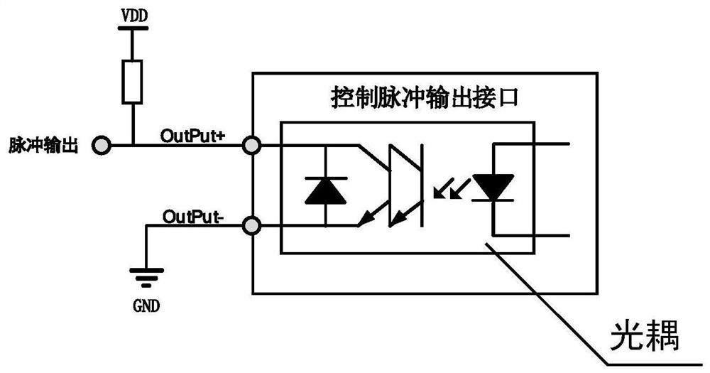
[0043] as attached figure 2 As shown, the optical fiber sensor pulse input interface includes an optocoupler isola...


PUM


Abstract

The invention discloses a multi-path position comparison output device based on an FPGA, the device is composed of a key operation panel, an LED display panel, a general ARM controller and a general FPGA device, the general FPGA device is provided with an optical fiber sensor pulse input interface, a multi-path control pulse output interface and an incremental encoder interface, and through the parallel processing characteristic of the FPGA, high-speed multi-path position comparison of a plurality of products on a production line is completed, pulse control signals meeting requirements are generated, and high-speed ordered control over a plurality of cameras is achieved. Meanwhile, universal FPGA logic processing is adopted so that the device can be implemented on various FPGA platforms in principle, including the FPGA with lower price, and the problem of higher cost of the current position comparator is solved.

Description

technical field [0001] The invention relates to the technical field of measurement and control, in particular to an FPGA-based multi-channel position comparison output device. Background technique [0002] With the rapid development of visual recognition technology, the production line began to use high-speed cameras to conduct quality inspections on product shape features or nameplate information, so as to realize that each product should be inspected thoroughly. In order to avoid the randomness of the detection, multiple cameras will be used to take pictures and compare samples at different positions for the same product. The following implementation is usually adopted, using the fiber optic sensor as the initial signal, when the product passes through the fiber sensor, the position of the product is latched and recorded, and in the subsequent movement, it is periodically checked whether the product has reached any of the camera positions, and if so, the corresponding cont...

Claims


Application Information

Patent Timeline
IPC IPC(8): G05B19/042
CPCG05B19/0423G05B2219/24215
Inventor 周向东唐小琦张庆祥陈英滔宋宝谭辉郑晓泽汤胜水周少峰
Owner GUANGDONG SAMSUN TECH CO LTD
Learn More