Conductive terminal
一种导电端子、合金镀层的技术,应用在接触部件等方向,能够解决端子使用寿命短、易被电解腐蚀、抗电解腐蚀性能不佳等问题
- Summary
- Abstract
- Description
- Claims
- Application Information
AI Technical Summary
Problems solved by technology
Method used
Image

Examples
no. 1 approach
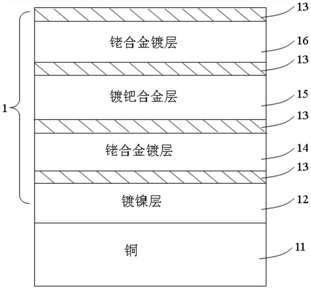
[0026] Please refer to figure 1 Shown is the first embodiment of the present invention, a conductive terminal (not marked), which is made of metal copper plate 11, and the shown conductive terminal includes a contact area for mating with a mating connector (not shown). The contact area is electroplated on the surface of the metal copper plate 11 to form a metal coating 1, and the metal coating 1 is electroplated sequentially from the surface of the metal copper plate 11: a nickel-plated layer 12, a gold-plated layer 13, and a first rhodium alloy coating 14 , gold-plated layer 13, first corrosion-resistant layer 15, gold-plated layer 13, second rhodium alloy plated layer 16 and gold-plated layer 13. The thickness of the first rhodium alloy coating 14 is equal to the thickness of the second rhodium alloy coating 16 . The first corrosion-resistant layer 15 is a palladium-plated layer or a palladium alloy-plated layer or a gold-plated layer or a silver-plated layer or a platinum-...
Embodiment approach
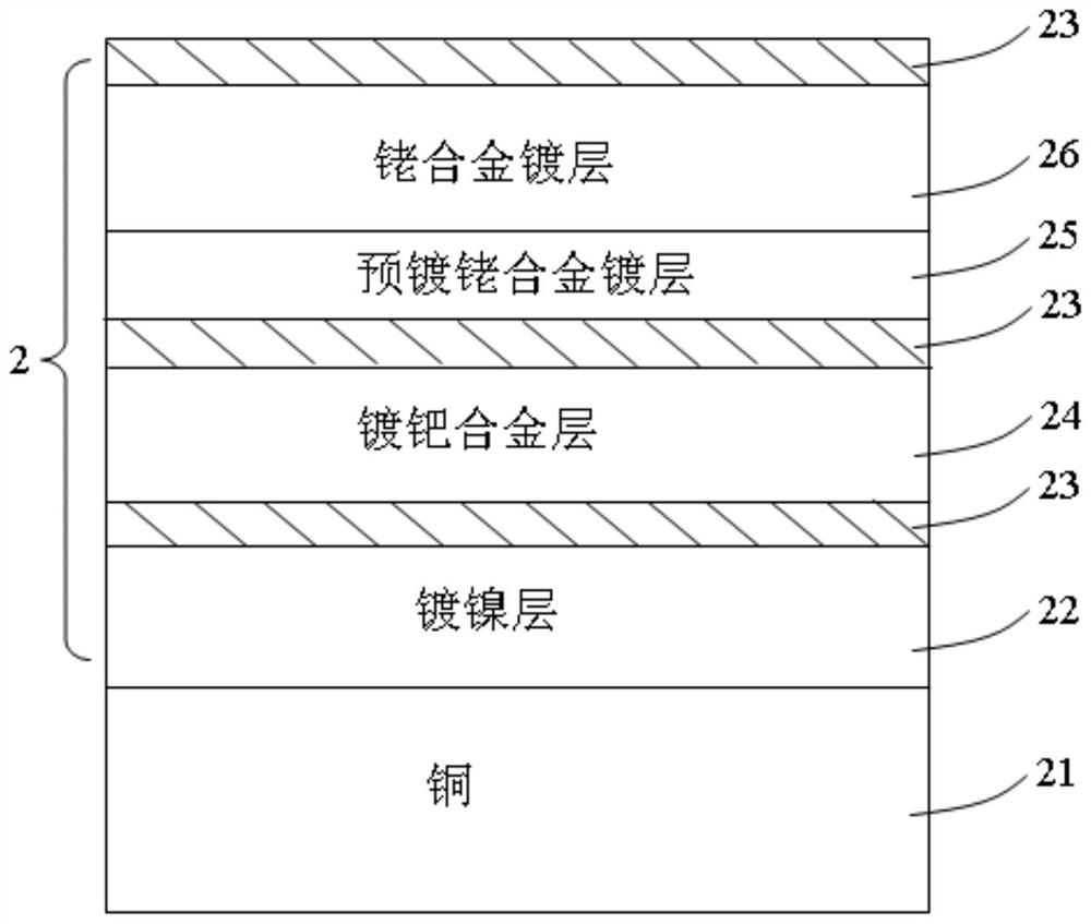
[0029] Please refer to figure 2 Shown is the second embodiment of the present invention, a conductive terminal (not marked), which is made of metal copper plate 21, the conductive terminal shown includes a contact area for docking with a mating connector (not shown), The contact area is electroplated on the surface of the metal copper plate 21 to form a metal coating 2, and the metal coating 2 is electroplated sequentially from the surface of the metal copper plate 21: a nickel-plated layer 22, a gold-plated layer 23, and a first corrosion-resistant layer 24 , gold-plated layer 23, the first rhodium alloy plated layer 25, the second rhodium alloy plated layer 26 and the gold-plated layer 23, wherein the nickel-plated layer 22 and the first corrosion-resistant layer 24 are corrosion-resistant layers and have chemical corrosion properties. In this embodiment, the thickness of the first rhodium alloy coating 25 is less than the thickness of the second rhodium alloy coating 26, s...
no. 3 approach
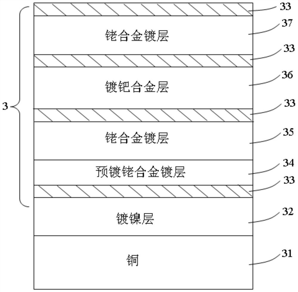
[0030] Please refer to image 3 Shown is the third embodiment of the present invention, a conductive terminal (not marked), which is made of metal copper plate 31, the conductive terminal shown includes a contact area for docking with a mating connector (not shown), The contact area is electroplated on the surface of the metal copper plate 31 to form a metal coating 3, and the metal coating 3 is electroplated sequentially from the surface of the metal copper plate 31: a nickel-plated layer 32, a gold-plated layer 33, and a first rhodium alloy coating 34 , the second rhodium alloy plating layer 35, the gold plating layer 33, the first corrosion resistant layer 36, the gold plating layer 33, the third rhodium alloy plating layer 37 and the gold plating layer 33. In this embodiment, three layers of rhodium alloy coatings (including the first, second and third rhodium alloy coatings) are electroplated, which have better electrolytic corrosion resistance. The functions of other pl...
PUM
 Abstract
Description
Claims
Application Information
 - Generate Ideas
- Intellectual Property
- Life Sciences
- Materials
- Tech Scout
- Unparalleled Data Quality
- Higher Quality Content
- 60% Fewer Hallucinations
Browse by: Latest US Patents, China's latest patents, Technical Efficacy Thesaurus, Application Domain, Technology Topic, Popular Technical Reports.
© 2025 PatSnap. All rights reserved.Legal|Privacy policy|Modern Slavery Act Transparency Statement|Sitemap|About US| Contact US: help@patsnap.com