
Driving protection circuit

A driving protection circuit, driving protection technology, applied in the direction of circuits, electrical components, electronic switches, etc., can solve problems such as fried tubes, difficult pull-down resistors, balanced control drive crosstalk, etc.

Pending Publication Date: 2021-09-10
成都氮矽科技有限公司
View PDF0 Cites 2 Cited by
  • Summary
  • Abstract
  • Description
  • Claims
  • Application Information

AI Technical Summary

Problems solved by technology

[0003] In view of this, the present application provides a driving protection circuit to improve the size of the pull-down resistance in the existing driving circuit, which is not easy to carry out balance control and existing driving crosstalk, and the threshold voltage is lower than that of the traditional silicon MOS tube. question

Method used


Image

  • Driving protection circuit
  • Driving protection circuit
  • Driving protection circuit

Examples


Embodiment Construction

[0020] The technical solutions in the embodiments of the present application will be clearly described below in conjunction with the accompanying drawings. In the case of no conflict, the following embodiments and their technical features can be combined with each other.

[0021] In the existing drive circuit, although the external pull-down resistor with large resistance can attenuate the LC resonance, and can reduce EMI and EMC, but the pull-down resistor is large, and the drive is greatly affected by the rate of change of the voltage (dv / dt). A certain degree of driving crosstalk is generated in the driving circuit, which may even cause the FET in the driving circuit to turn on by mistake and cause the tube to explode.

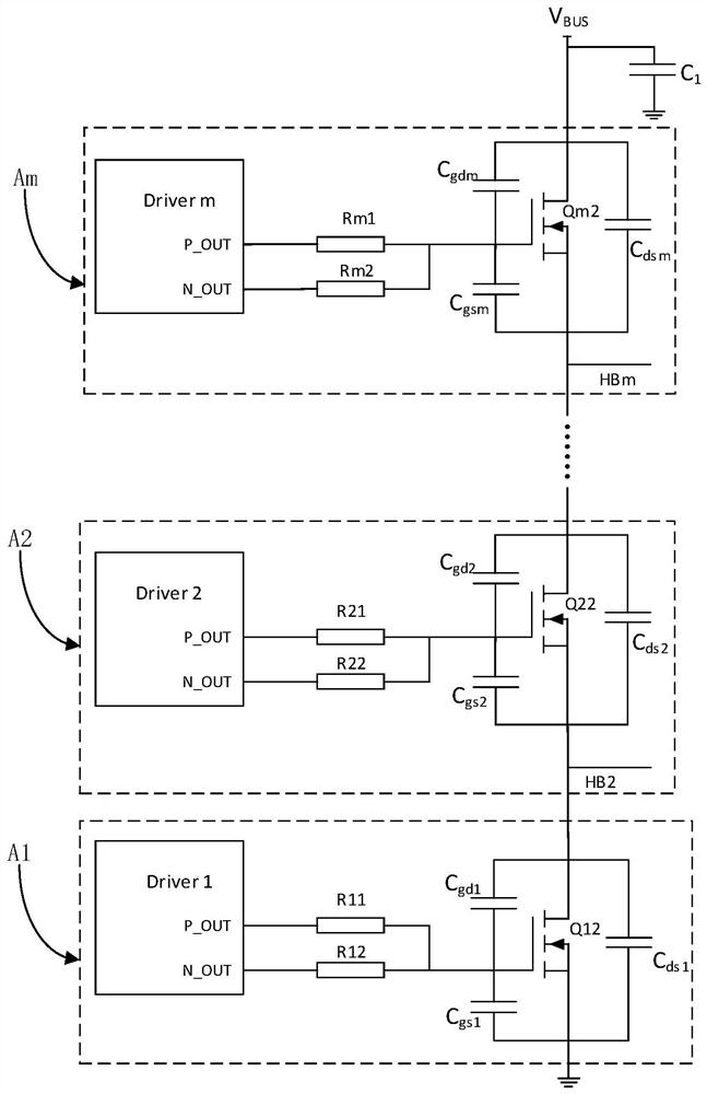
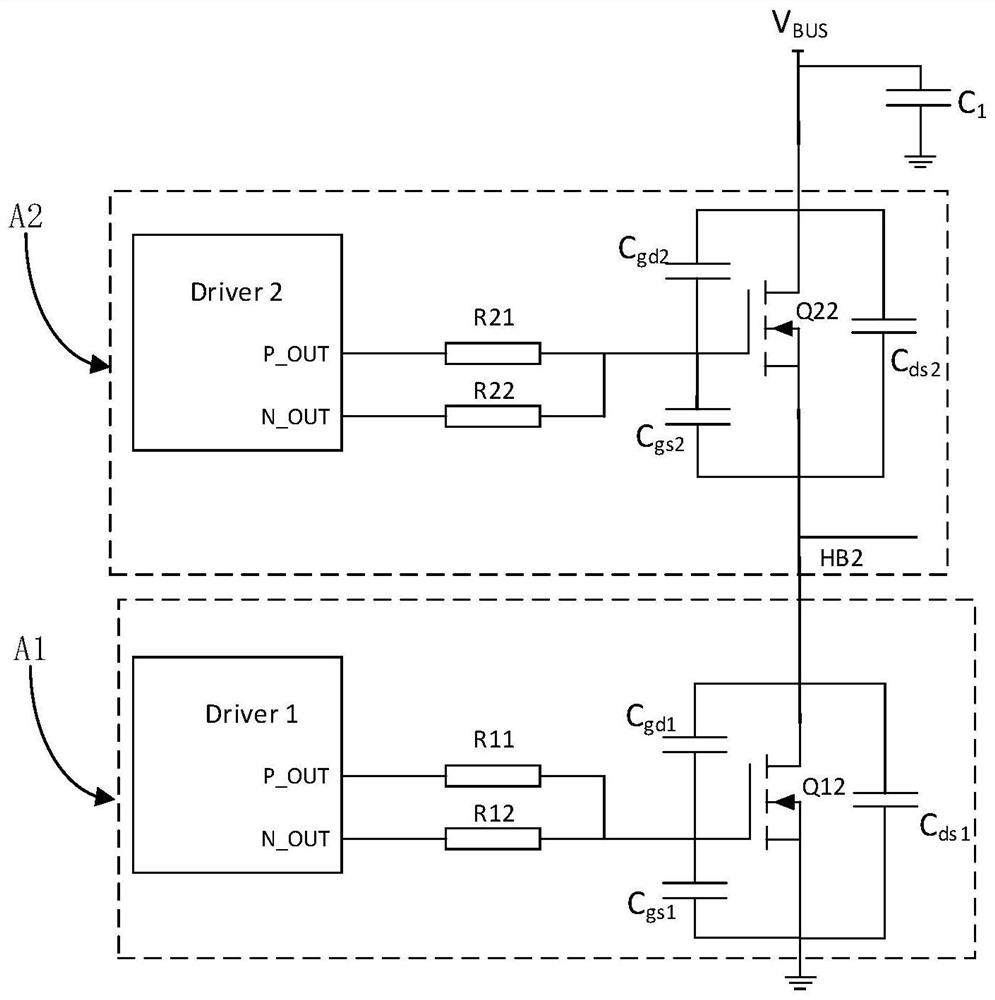
[0022] Specifically, such as figure 1 Shown is a schematic diagram of the circuit structure of a drive circuit in the prior art, the drive circuit includes m first drive modules A1, A2, ..., Am electrically connected, m is an integer greater than or equal t...


PUM


Abstract

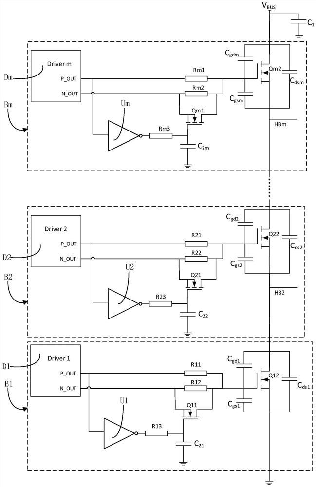
The invention discloses a driving protection circuit, the driving protection circuit comprises at least two driving protection modules which are electrically connected, each driving protection module comprises a driving module, a pull-down resistor, an inverting circuit, a first switch tube and a second switch tube, a first output end of the driving module is connected with a first end of the second switch tube, a first output end of the driving module is connected with a first end of the first switch tube through the phase inverting circuit, a second output end of the driving module is connected with a third end of the first switch tube, and a second end of the first switch tube is connected with a first end of the second switch tube. The pull-down resistor is connected with the first switch tube in parallel, and the second end of the second switch tube is connected with the third end of the second switch tube in the adjacent previous driving protection module. According to the driving protection circuit, ringing, EMI and EMC can be effectively suppressed, and tube explosion caused by driving crosstalk and mistaken opening of a switching tube is avoided.

Description

technical field [0001] The present application relates to the technical field of power electronics, in particular to a driving protection circuit. Background technique [0002] For the Demo (demonstration, prototype or demo version) of the LLC circuit (that is, the resonant circuit), it is easy to explode the tube during debugging. Specifically, the external large-value pull-down resistor in the drive circuit has an attenuation effect on the LC resonance, and can reduce electromagnetic interference (Electromagnetic Interference, EMI) and electromagnetic compatibility (Electromagnetic Compatibility, EMC); The rate of change (dv / dt) has a greater influence and will generate a certain degree of drive crosstalk in the drive circuit. Especially when a Field-Effect Transistor (FET) with a small threshold voltage is used in the driving circuit, it is easy to turn on the Field-Effect Transistor by mistake, thereby causing the tube to explode. Contents of the invention [0003] I...

Claims


Application Information

Patent Timeline
Patent Type & Authority Applications(China)
IPC IPC(8): H03K17/081H03K17/687
CPCH03K17/08104H03K17/687
Inventor 李鑫葛征良罗鹏
Owner 成都氮矽科技有限公司
Learn More