
Transmission line for radiofrequency range current

A radio frequency range, transmission line technology, applied in the field of transmission lines, which can solve problems such as limited beam coverage, limited space, and inactive display status

Active Publication Date: 2021-09-10
HUAWEI TECH CO LTD
View PDF5 Cites 0 Cited by
  • Summary
  • Abstract
  • Description
  • Claims
  • Application Information

AI Technical Summary

Problems solved by technology

However, if the antenna is placed away from the frame, the radiating opening in the metal frame must be relatively large, however large openings in the metal frame are to be avoided for aesthetic reasons and mechanical robustness
Additionally, radiation from mmWave antennas placed far from the frame is shadowed by conductive components of the mobile device, causing mmWave beamforming to deflect, limiting beam coverage
[0006]Furthermore, the tendency for very large displays to cover as much electronic equipment as possible makes the space available for different antennas very limited, forcing a significant reduction in the size of the antenna array and its Impaired performance, or most of the display is inactive

Method used


Image

  • Transmission line for radiofrequency range current
  • Transmission line for radiofrequency range current
  • Transmission line for radiofrequency range current

Examples


Embodiment Construction

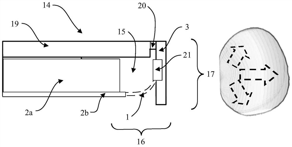
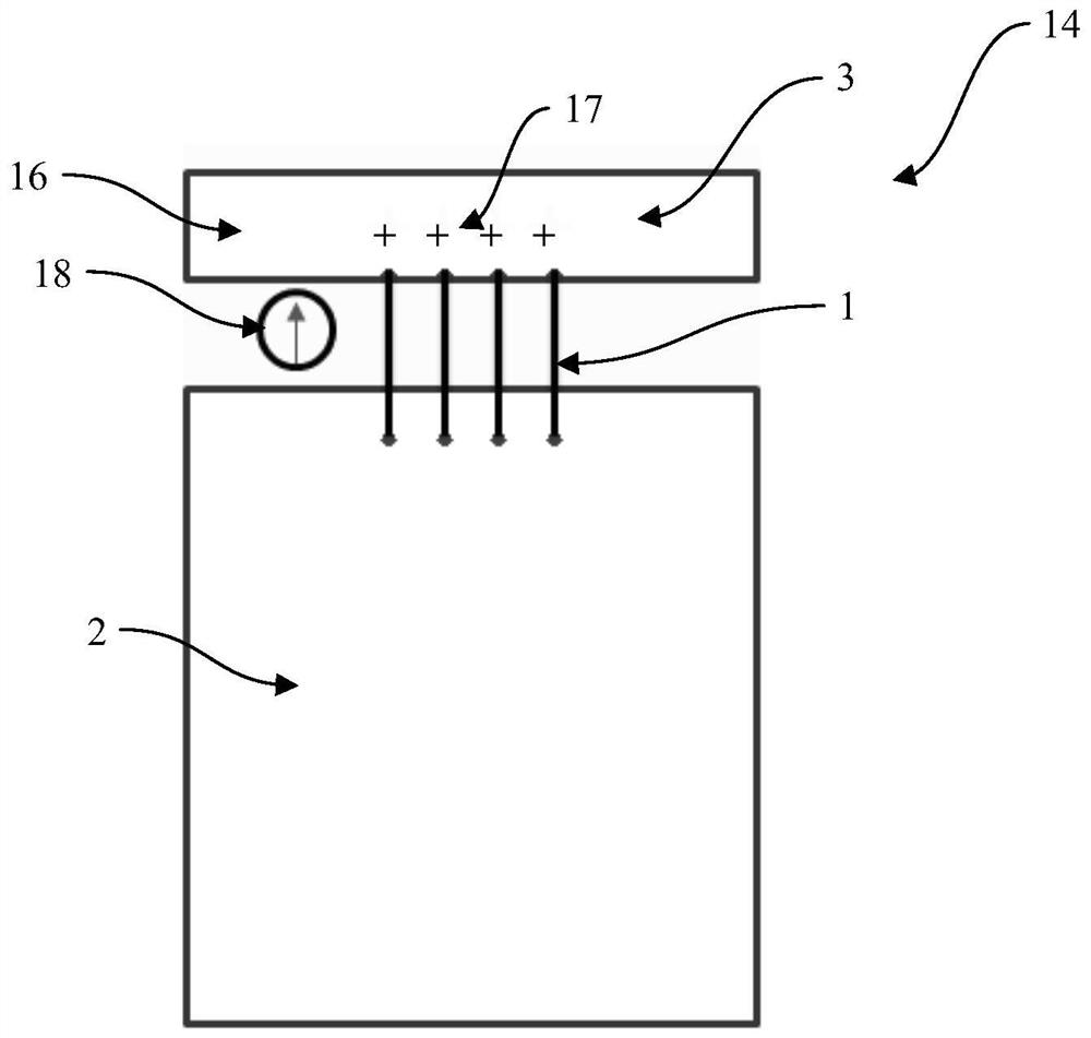
[0045] Figure 1a-1b An electronic device 14 is shown comprising: a display 19 , a first conductive element 2 , a second conductive element 3 , a first antenna 16 and a second antenna 17 . The first conductive element 2 may be a device chassis 2a or a printed circuit board (PCB for short) 2b, and the second conductive element 3 may be a metal frame. The display 19 and the metal frame 3 may at least partially surround the device chassis 2a and the printed circuit board 2b. The radio frequency radiation generated by the first antenna 16 and the second antenna 17 can be transmitted through a dielectric gap 20 separating the display 19 from the metal frame 3 .

[0046] The first conductive element 2 and the second conductive element 3 are separated by a non-conductive volume 15 within which the first antenna 16 and the second antenna 17 are at least partially arranged. A first transmission line 18 connects the first conductive element 2 to the first antenna 16 across the non-con...


PUM


Abstract

Disclosed is a transmission line (1) for transmitting radiofrequency range current between a first conductive element (2) and a second conductive element (3). The transmission line (1) comprises a signal current line (4) and at least one return current line (5), and the signal current line (4) and the return current line(s) (5) extend in parallel. Each current line (4, 5) comprises at least one first segment (6) and at least one second segment (7). Each first segment (6) is partially aligned with at least one adjacent second segment (7), aligned segments being separated by a first dielectric gap (8), and each aligned first segment (6) and second segment (7) forming a capacitive coupling across the first dielectric gap (8). This solution enables a transmission line which provides only small capacitive loading onto its surroundings, and which therefore can extend, e.g., through an antenna element without significantly affecting the performance of the antenna element.

Description

technical field [0001] The invention relates to a transmission line for transmitting electric current in the radio frequency range between a first conductive element and a second conductive element. Background technique [0002] Future electronic devices will need to support millimeter wave frequency bands such as 28GHz and 42GHz, as well as frequency bands below 6GHz to accommodate higher data rates. However, the volume reserved for all antennas in a mobile electronic device is very limited, and ideally the added mmWave antenna should fit into the same volume as the sub-6GHz antenna. Increasing the volume reserved for antennas would make electronic devices larger, bulkier and less attractive to users. Current mmWave antennas either require this extra volume, or significantly reduce the sub-6GHz antenna's efficiency if placed in the same volume. [0003] The current sub-6GHz antenna is located on the metal frame of the electronic device, which belongs to the type of capaci...

Claims


Application Information

Patent Timeline
IPC IPC(8): H01P1/203H01P1/201H01Q1/24H01Q1/52H01Q5/307H01Q21/28
CPCH01P1/20363H01Q1/521H01Q1/243H01Q5/307H01Q21/28H01P1/2013
Inventor 亚力山大·克瑞普科夫维勒·维卡里雷斯特·蒙托亚 莫雷诺朱哈·阿拉-劳里纳霍珍妮·伊尔沃宁贾里 克里斯蒂安·范 温特格姆
Owner HUAWEI TECH CO LTD
Learn More