Multi-material 3D printing method and micro-flow extrusion type printer based on multi-material 3D printing method

A 3D printing, multi-material technology, applied in the field of 3D printing, can solve problems such as printing delay error, material delay, printing deviation, etc.

Active Publication Date: 2021-09-14
HEBEI UNIV OF TECH
View PDF6 Cites 0 Cited by
  • Summary
  • Abstract
  • Description
  • Claims
  • Application Information

AI Technical Summary

Problems solved by technology

Due to the stage of mixing materials and conveying materials from the barrel to the print nozzle in the multi-material printing process, there is a material delay phenomenon, which causes the path information of the print nozzle to produce an offset distance, resulting in a delay error in printing
figure 1 Schematic diagram of the position where the material composition changes for dual-material printing, where a represents the schematic diagram of the position where the material composition changes under ideal conditions, and b represents the schematic diagram of the position where the material composition changes in the actual situation; each point in the figure represents the position of the printed The path information of the nozzle, at the poin

Method used


Image

  • Multi-material 3D printing method and micro-flow extrusion type printer based on multi-material 3D printing method
  • Multi-material 3D printing method and micro-flow extrusion type printer based on multi-material 3D printing method
  • Multi-material 3D printing method and micro-flow extrusion type printer based on multi-material 3D printing method

Examples


Embodiment Construction

[0031] Specific examples of the present invention are given below. The specific embodiments are only used to further describe the present invention in detail, and do not limit the protection scope of the claims of the present application.

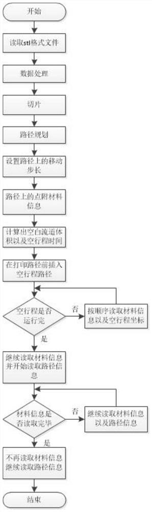
[0032] The present invention is a multi-material 3D printing method (method for short, see Figure 2-3 ), including the following:

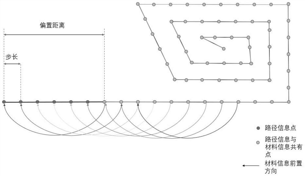
[0033] 1. Read the stl format file of the object to be printed, perform data processing on the stl format file, and then slice the processed object to be printed; plan the path of the print head according to the structure of the object to be printed, and obtain the path information of the print head , that is, the path information of the forming platform; set the moving step on the path, and add material information to the points on the path; the moving step refers to the distance that the print nozzle moves each time, and set the movement according to the color change after mixing multiple materials step si...


PUM


Abstract

The invention relates to a multi-material 3D printing method and a micro-flow extrusion type printer based on the multi-material 3D printing method. The method comprises the following steps that 1, an stl format file of a to-be-printed object is read, the stl format file is processed and sliced, path planning is conducted on a printing nozzle, path information is obtained, a moving step length is set, and material information is added to points on the path; 2, the printer reads the material information, the printing nozzle does idle stroke motion in the period when a blank runner is filled with a mixture, the printing nozzle is located at the starting point of the path when the idle stroke motion is finished, the printer continues to read the material information and starts to read the path information, and a printing task is started; and 3, after the material information is read, the printer does not read the material information any more and continues to read the path information until the mixture in a charging barrel is completely extruded out, and the printing nozzle completes the whole printing task. The method can eliminate the delay error generated in the process of filling the blank runner with the mixture, and the printer is suitable for a ceramic functionally graded material.

Description

technical field [0001] The invention belongs to the technical field of 3D printing, and specifically relates to a multi-material 3D printing method and a microflow extrusion printer based on the method, which are mainly used for 3D printing of ceramic functionally graded materials. Background technique [0002] Desktop-level 3D printers generally print by fusion deposition. Although the printer is small, light and cheap, the material used is too single. It can only print with a single material, that is, a single color, and it is difficult to print parts made of functionally graded materials. The ceramic slurry is a non-Newtonian fluid and has the property of "shear thinning". The viscosity without stirring is 285pa.s. It is difficult for ordinary 3D printers to extrude high-viscosity ceramic slurry. [0003] The existing 3D printing process is based on the principle of single-material printing. The material information read by the printer corresponds to the path information ...

Claims


Application Information

Patent Timeline
IPC IPC(8): B28B1/00B28B13/02B28B17/00B33Y30/00B33Y40/10B33Y40/00B33Y50/00B33Y50/02
CPCB28B1/001B28B13/0235B28B17/0063B33Y30/00B33Y40/10B33Y40/00B33Y50/00B33Y50/02
Inventor 段国林韩硕彭壮壮
Owner HEBEI UNIV OF TECH
Why Eureka
Try Eureka