Bidirectional driving device of scraper conveyer and scraper conveyer

A technology of scraper conveyor and two-way drive, which is applied in the field of scraper conveyor and can solve problems such as the failure of scraper conveyor to operate normally

Active Publication Date: 2021-09-14
HUAINAN ZHENG COAL MACHINE SHUNLI MACHINERY
View PDF7 Cites 0 Cited by
  • Summary
  • Abstract
  • Description
  • Claims
  • Application Information

AI Technical Summary

Problems solved by technology

[0006] The technical problem to be solved by the present invention is that the sprocket of the driving device of the scraper conveyor in the prior art will cause the scraper conveyor to not operate normally when it runs in reverse , providing a two-way driving device for a scraper conveyor

Method used


Image

  • Bidirectional driving device of scraper conveyer and scraper conveyer
  • Bidirectional driving device of scraper conveyer and scraper conveyer
  • Bidirectional driving device of scraper conveyer and scraper conveyer

Examples


Embodiment 1

[0039] A two-way driving device for a scraper conveyor, such as image 3 and Figure 4 As shown, it includes a scraper chain 113, a sprocket 114, a drive unit (not shown) and a chain pressing roller.

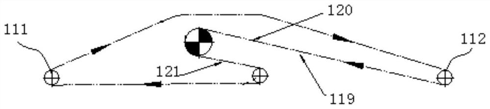
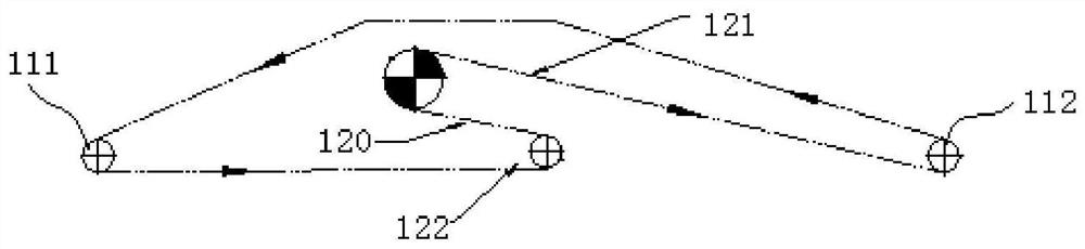
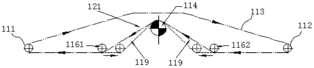
[0040] The scraper chain 113 is laid from the loading end 111 of the scraper conveyor to the unloading end 112 of the scraper conveyor through the pallet 115, then laid from the unloading end 112 to the sprocket 114, and then laid from the sprocket 114 to the loading end 111, finally forming a closed chain.

[0041]The sprocket 114 is located below the scraper chain 113, and the sprocket 114 is located in the middle between the loading end 111 and the unloading end 112 of the scraper conveyor. The chain winding of the sprocket 114 is improved from the original "S-shaped" layout to "W-shaped". .

[0042] In this embodiment, the drive unit includes a motor, a friction coupler and a reducer, the output shaft of the motor is connected with the friction coupler, the friction coupl...

Embodiment 2

[0050] This embodiment is a scraper conveyor, including the bidirectional driving device of the scraper conveyor in Embodiment 1.

[0051] When the scraper conveyor in this embodiment is in use, the drive unit is started, and the drive unit drives the sprocket 114 to rotate, thereby driving the scraper chain 113 to run. When reverse transport is required, the loose side 121 of the scraper chain 113 is adjusted by the first pusher unit 1171 or the second pusher unit 1172 , so that the scraper chain 113 at this position can be moderately tensioned and well meshed with the sprocket 114 . And the driving device in the present invention does not need to use other sprocket 114 tensioning devices, the driving device can be placed in the middle of the scraper conveyor, and two-way transportation can be realized at the same time.


PUM


Abstract

The invention discloses a bidirectional driving device of a scraper conveyor. The bidirectional driving device comprises scraper chains, chain wheels, a driving unit and chain pressing rollers; the scraper chains are laid from the loading end of the scraper conveyor to the unloading end, laid from the unloading end to the chain wheels and then laid from the chain wheels to the loading end, and the scraper chains form a closed chain; the chain wheels are located below the scraper chains and located between the loading end and the unloading end; the driving unit is connected with the chain wheels; the chain pressing rollers comprise a first chain pressing roller and a second chain pressing roller, and the first chain pressing roller and the second chain pressing roller are located on the two sides of the chain wheels; the first chain pressing roller and the second chain pressing roller move close to or away from the chain wheels so as to adjust the tensioning degree of the scraper chains on the two sides of the chain wheels. The invention further provides the scraper conveyor comprising the driving device. The device has the advantages that the middle-driven scraper conveyor can transport in two directions, normal and efficient working performance of the scraper conveyor is guaranteed, and meanwhile layout, installation and adjustment of the scraper conveyor in an underground coal mine site are greatly facilitated.

Description

technical field [0001] The invention relates to the technical field of scraper conveyors, in particular to a bidirectional drive device for scraper conveyors and a scraper conveyor. Background technique [0002] The scraper conveyor is a continuous action transport machine with a flexible body as the traction mechanism. The scraper conveyor is mainly used in the longwall coal mining face. It is currently the only transportation equipment in the longwall coal mining face. Coal transportation tasks. In addition, the function of the scraper conveyor is not only to transport coal and materials, but also can be used as the running track of the coal mining machine, so it has become an indispensable main equipment in the modern coal mining process. The scraper conveyor can keep running continuously, and the production can go on normally. Otherwise, the entire coal mining face will show a shutdown state, so that the entire production is interrupted. [0003] At present, the dome...

Claims


Application Information

Patent Timeline
Patent Type & Authority Applications(China)
IPC IPC(8): B65G19/18B65G23/06B65G19/20B65G19/30E21F13/06
CPCB65G19/18B65G23/06B65G19/20B65G19/30E21F13/06
Inventor 王玲闵宏潘玥
Owner HUAINAN ZHENG COAL MACHINE SHUNLI MACHINERY
Why Eureka
Try Eureka