Air pipe connector for tight-lock coupler and coupler thereof

A connector and tight connection technology, which is applied in the field of rail transit, can solve the problems of short telescopic guide of the valve head of the air duct connector, complex structure of the main air duct connector, and many structural parameters of the air duct connector, so as to prevent expansion and contraction Effects of short guide, fewer required parts, and simplified structure

Pending Publication Date: 2022-02-01
江苏肯耐特轨道装备科技有限公司
View PDF1 Cites 0 Cited by
  • Summary
  • Abstract
  • Description
  • Claims
  • Application Information

AI Technical Summary

Problems solved by technology

[0003] The structure of the existing main air pipe connector is relatively complicated. The prior art CN204284743U discloses a close-fit air pipe connector for couplers, which uses the pressure of a pressure spring to make the rubbers of the two valve ports close to each other for sealing. The connection adopts the pressure compression tappet spring when the coupler is connected to realize the connection of the gas path. This prior art uses two different parts to set up the spring telescopic mechanism at the same time. The number of structural parts is large and complicated, which is not easy to assemble; The more complex the structure of the air duct connector, the more structural parameters that affect the performance of the air duct connector
Moreover, the telescopic guide of the valve head of this air duct connector is short, and there is a risk of popping out and sticking after unhooking

Method used


Image

  • Air pipe connector for tight-lock coupler and coupler thereof
  • Air pipe connector for tight-lock coupler and coupler thereof
  • Air pipe connector for tight-lock coupler and coupler thereof

Examples


Embodiment 1

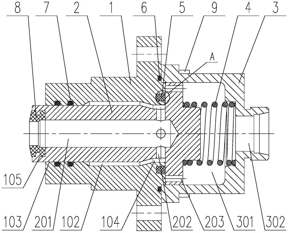
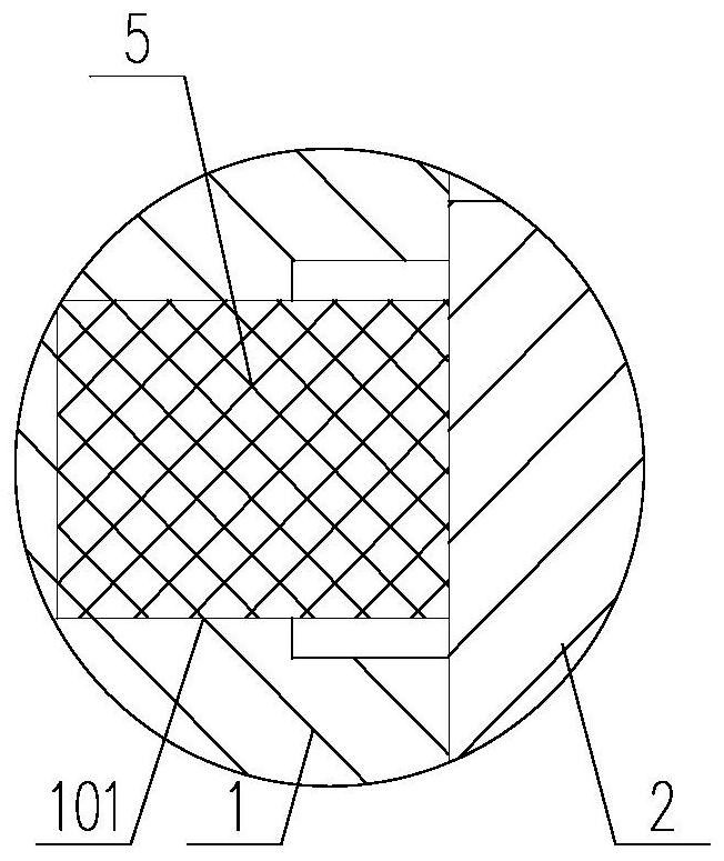
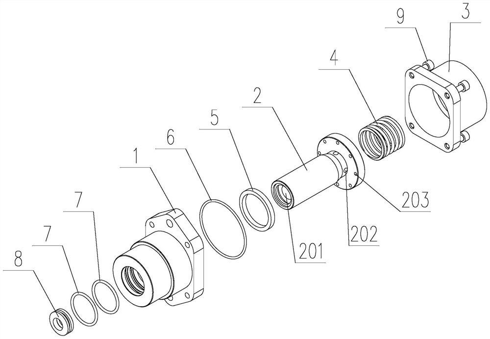
[0037] Such as Figure 1 ~ Figure 3 As shown, a air duct connector for a tight-fitting coupler includes a valve stem 2, a valve body 1 that fits with the outer circular surface of one end of the valve stem 2 and is tightly matched with it, and a large valve sleeve that is sleeved at the other end of the valve stem 2. The connecting seat 3 fixedly connected to the valve body 1 on the outer circular step, the elastic member 4 elastically contacting the valve stem 2 and the connecting seat 3, and the gasket 5 sealing the end face of the large outer circular step and the end face of the valve body 1, all The end of the valve stem 2 away from the connecting seat 3 is equipped with a valve port rubber 8, and one end of the valve stem 2 communicates with the outside world through the inner hole of the valve port rubber 8, and the other end communicates with the outside of the valve stem 2 through a radial communication hole 202. The main hole 201 connected to the cylindrical surface;...

Embodiment 2

[0045] In this embodiment, the elastic member 4 is preferably a compression spring.

[0046] Such as Figure 1 ~ Figure 3 As shown, a air duct connector for a tight-fitting coupler includes a valve stem 2, a valve body 1 that fits with the outer circular surface of one end of the valve stem 2 and is tightly matched with it, and a large valve sleeve that is sleeved at the other end of the valve stem 2. The connecting seat 3 fixedly connected to the valve body 1 on the outer circular step, the pressure spring elastically abutting the valve stem 2 and the connecting seat 3, and the sealing gasket 5 sealing the end face of the large outer circular step and the end face of the valve body 1, said The end of the valve stem 2 away from the connecting seat 3 is equipped with a valve port rubber 8, and the valve stem 2 is provided with four valve ports. The main hole 201 connected to the outer cylindrical surface;

[0047] Under the pre-pressure of the elastic member 4, the cylindrica...

Embodiment 3

[0063] In the present embodiment, the implementation manner of the elastic member 4 is as follows:

[0064] At the end of the valve stem located in the inner cavity of the connecting seat 3, there are a plurality of installation holes evenly distributed along the circumference of the valve stem axis, and on the inner wall of the connection seat 3 opposite to the end face of the valve stem, there are installation holes that are distributed in the same manner as the installation holes. Consistent positioning holes, installation holes and positioning holes correspond one by one, and a tension spring is arranged between them, and the two ends of the tension spring are respectively inserted into the positioning hole and the installation hole.

[0065] In this way, multiple functional and structurally consistent spring members are installed at a position that requires elastic members, and they are evenly distributed along the axis of the valve stem to improve the uniformity of the fo...


PUM


Abstract

The invention discloses an air pipe connector for a tight-lock coupler and a coupler thereof, relates to the technical field of rail transit, and solves the technical problems that an existing air pipe connector is inconvenient to assemble and the like. The air pipe connector comprises a valve rod, a valve body matched with one end of the valve rod, a connecting base arranged on a large outer circle step at the other end of the valve rod in a sleeving mode and fixedly connected with the valve body, an elastic piece enabling the valve rod to elastically abut against the connecting base and a sealing gasket for sealing the end face of the large outer circle step and the end face of the valve body, and valve port rubber is installed at one end of the valve rod. The valve rod is provided with a radial communicating hole and a main hole. The valve port rubber is arranged on the valve rod, so that the valve port rubber can move along with the movement of the valve rod, the elastic piece arranged at one position is used for achieving mutual attaching of the valve port rubber and automatic locking of the air pipe connector when air is communicated, the structure of the air pipe connector is simplified, needed parts are reduced, and the air pipe connector is convenient to process and assemble.

Description

technical field [0001] The invention relates to the technical field of rail transit, in particular to an air duct connector for a close-fit coupler and a coupler thereof. Background technique [0002] In order to improve the automation of the coupling and uncoupling of two adjacent carriages of EMUs and subway vehicles, a fully automatic coupler system is widely used in the industry at present. After the two couplers are unhooked and disengaged, the air passages can be automatically locked to prevent air leakage; this kind of mechanism that automatically connects the air passages when they are connected, and automatically locks the air passages after disengagement is called an air duct connector in the industry. [0003] The structure of the existing main air pipe connector is relatively complicated. The prior art CN204284743U discloses a close-fit air pipe connector for couplers, which uses the pressure of a pressure spring to make the rubbers of the two valve ports close t...

Claims


Application Information

Patent Timeline
Patent Type & Authority Applications(China)
IPC IPC(8): F16L29/04
CPCF16L29/04
Inventor 肖声唐飞李向福
Owner 江苏肯耐特轨道装备科技有限公司
Why Eureka
Try Eureka