Light fabricated steel structure building

A prefabricated, steel structure technology, applied in the direction of construction, building construction, etc., can solve problems such as cumbersome operation process

Active Publication Date: 2021-09-14
东莞市联泰钢构有限公司
View PDF5 Cites 3 Cited by
  • Summary
  • Abstract
  • Description
  • Claims
  • Application Information

AI Technical Summary

Problems solved by technology

[0004] For the related technologies mentioned above, when installing beams and columns, it is usually necessary to drive in a large number of bolts and nuts to achieve mutual connection. During this period, welding and reinforcement may also be involved. The operation process is cumbersome, and the components There is still a lot of room for improvement in the installation efficiency between

Method used


Image

  • Light fabricated steel structure building
  • Light fabricated steel structure building
  • Light fabricated steel structure building

Examples


Embodiment 1

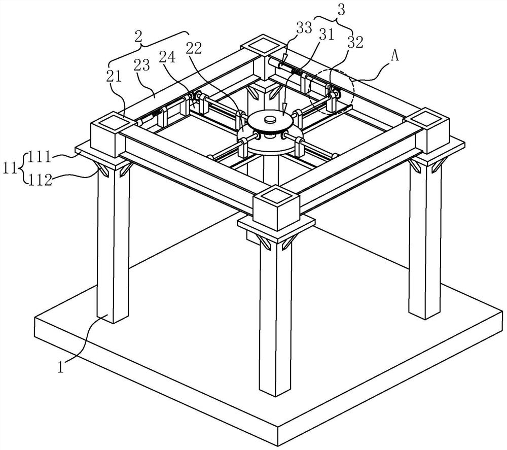
[0039] Example discloses a prefabricated lightweight steel construction of the present application. Refer figure 1 The building structure 1 and comprises a plurality of pillars disposed upright on the crossbeam 12, wherein, in the present embodiment, the number of the column 1 is provided specifically four, four columns 1 arranged in the vertical direction, and was a rectangular arrangement, the bottom end of the column 1 may be fixedly mounted to the foundation, mounting the column 1 is the prior art, it is not repeated here.

[0040] Column 1 for supplying supporting crossbeam 2, specifically, the top of the column 1 is provided with supporting platforms 11, wherein the supporting platform 11 comprises a supporting plate 111 and the reinforcing bars 112. Supporting plate 111 disposed in the horizontal direction, the outer edge contour shape through the upper supporting plate 111 is provided with a socket hole, the hole socket contour shape adapted to the pillar 1, via the suppor...

Embodiment 2

[0059] Refer Figure 5 The present embodiment is different from Embodiment 1 in that, the building structure further comprises an input shaft 311 adjacent to the engaging component 4. In particular, the engaging component 4 is disposed on the mounting platform 22, with the engaging component 4 to lock the input shaft 311 is fixed to reduce the portion of the socket 21 and the lock pillar 1 is engaged, the input shaft 311 and the possibility of rattling of loose offset.

[0060] Specifically, the fastening assembly 4 includes a first clamping portion 41 and the second clamping portion 42, the first clamping portion 41 and the second holding portion 42 are connected to slip crossbeam 2, wherein the mounting platform 22 outward from the top of the recess 221 is provided with a chute, the chute 221 adjacent the input shaft 311.

[0061] Further, the first clamping portion 41 includes a first connecting arm 411, a second connecting arm 412, and a first arcuate clamp arm 413, connected t...


PUM


Abstract

The invention relates to the field of fabricated buildings, in particular to a light fabricated steel structure building. According to the technical scheme, the light fabricated steel structure building is characterized by comprising a plurality of stand columns, a cross beam frame and a locking assembly, the cross beam frame is provided with sleeving parts, the stand columns are provided with a bearing platform, the sleeving parts are matched with the stand columns in a sleeving manner, the bearing platform bears the sleeving parts, and the locking assembly comprises a power input part, transmission parts and locking parts; and the power input part and the transmission parts are arranged on the cross beam frame, one ends of the transmission parts are connected with the power input part, the other ends of the transmission parts are connected with the locking parts, the multiple sets of transmission parts are correspondingly connected with the multiple sets of locking parts, the locking parts are movably arranged on the sleeving parts, locking holes are horizontally formed at the tops of the stand columns in a penetrating manner, and the locking parts are matched with the locking holes in an inserted manner. The power input part is used for outputting power, the transmission parts are used for transmitting the power to the locking parts so that the locking parts can be movably inserted into the locking holes, and the building has the the effect of improving the installation efficiency of a component.

Description

Technical field [0001] The present application relates to the field of prefabricated construction, particularly, to a lightweight steel construction fabricated. Background technique [0002] With the rapid development of modern architectural diversity, prefabricated buildings are widely used, fabricated building is a set of standardized design, industrial production, assembly of construction, information management and intelligent application as one of modern industrial building, has assembled fast, cost-effective and energy saving features, is the forefront of the development direction of the construction industry. [0003] At present, widely used in assembly plants and building stadiums and other large buildings, which mainly uses light steel construction of the supporting body, here, including steel columns, beams and a roof member, wherein the column in the vertical direction fixedly mounted in the foundation, the plurality of the pillar, a plurality of uniformly arranged upr...

Claims


Application Information

Patent Timeline
Patent Type & Authority Applications(China)
IPC IPC(8): E04B1/24
CPCE04B1/24E04B1/2403
Inventor 黄荣铃
Owner 东莞市联泰钢构有限公司
Why Eureka
Try Eureka