Intelligent windowsill

A window sill, intelligent technology, applied in the direction of windows/doors, door/window accessories, doors/windows that can be stretched, etc., can solve the problems of accumulation, rainwater brought into the room, floor rainwater, etc.

Pending Publication Date: 2021-09-14
曾聪
View PDF6 Cites 0 Cited by
  • Summary
  • Abstract
  • Description
  • Claims
  • Application Information

AI Technical Summary

Problems solved by technology

[0003] At present, due to the accelerated pace of modern life, office workers spend less and less time at home, so that forgetting to close the windows before going out has become a very common phenomenon in life, and in the rainy season, sudden rain is often unpredictable. When it rains, forgetting to close the windows will cause rainwater to be brought into the room, resulting in the accumulation of rainwater on the indoor floor. Therefore, a smart window sill is proposed to solve the above-mentioned problems.

Method used


Image

  • Intelligent windowsill
  • Intelligent windowsill
  • Intelligent windowsill

Examples


Embodiment 1

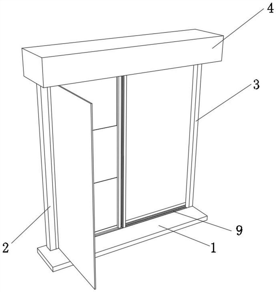
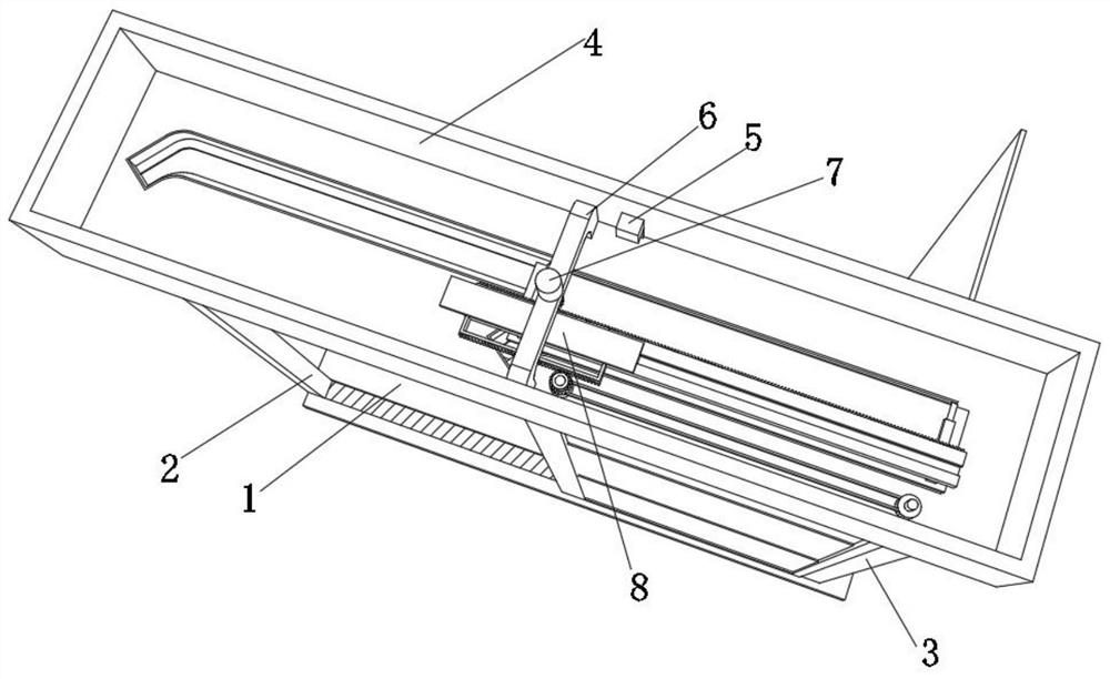
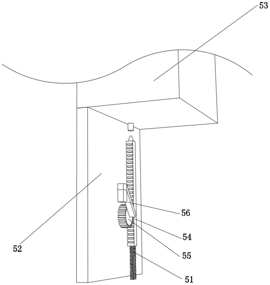
[0032] A smart window sill such as Figure 1-Figure 5 As shown, including the base 1, the upper surface of the base 1 is fixedly connected with the left support rod 2 and the right support rod 3 respectively, the left support rod 2 is located on the left side of the right support rod 3, the left support rod 2 and the right support rod 3 The top of the support box 4 is fixedly connected by the lower surface of the support box 4, the front wall of the support box 4 is provided with a control mechanism 5, the bottom wall of the support box 4 is fixedly connected with a fixed rod 6, and the upper surface of the fixed rod 6 is provided with an adjustment mechanism 7 , the lower surface of the fixed rod 6 is fixedly connected with a support plate 8, and the upper surface of the bottom platform 1 is located between the left support rod 2 and the right support rod 3 to have a chute 9.

[0033] The support to the adjustment mechanism 7 can be played by the fixed rod 6 and the support p...

Embodiment 2

[0043] Such as Figure 6-Figure 8 As shown, on the basis of Embodiment 1, in this embodiment, the adjusting device 10 includes a small tooth plate 101 and a second window 102, the surface of the small tooth plate 101 is fixedly connected with the surface of the meshing tooth plate 73, and the small tooth plate The surface of 101 is in contact with the surface of driven gear 103, and the axis of driven gear 103 is fixedly connected with first transmission shaft 104, and the bottom end of first transmission shaft 104 runs through the top of second window 102 and connects with the top of second window 102 Internal rotation connection, the surface of the first transmission shaft 104 is fixedly connected with the first pulley 105 above the second window 102, the surface of the first pulley 105 is connected with the surface of the second pulley 106 through a belt, and the shaft of the second pulley 106 The center is fixedly connected with a second transmission shaft 107 , and the bo...


PUM


Abstract

The invention relates to smart home, and discloses an intelligent windowsill. The windowsill comprises a bottom table, the upper surface of the bottom table is fixedly connected with a left supporting rod and a right supporting rod, the left supporting rod is located at the left side of the right supporting rod, and the top end of the left supporting rod and the top end of the right supporting rod are fixedly connected through the lower surface of a supporting box; and a control mechanism is arranged on the front wall in the supporting box, a fixing rod is fixedly connected to the bottom wall in the supporting box, an adjusting mechanism is arranged on the upper surface of the fixing rod, and a supporting plate is fixedly connected to the lower surface of the fixing rod. According to the intelligent windowsill, the moisture content in the air can be detected at any time through a temperature control mechanism so as to detect whether rain and snow occur or not, so that starting of an adjusting mechanism can be controlled, the purpose of closing a window can be achieved, and the situation that rain and snow which are taken out suddenly enter a room, and consequently the indoor environment is affected is prevented.

Description

technical field [0001] The invention relates to a smart home, in particular to a smart window sill. Background technique [0002] Smart home is based on the residence as a platform, using integrated wiring technology, network communication technology, security technology, automatic control technology, audio and video technology to integrate the facilities related to home life, build an efficient management system for residential facilities and family schedules, and improve Home safety, convenience, comfort, artistry, and to achieve an environmentally friendly and energy-saving living environment. [0003] At present, due to the accelerated pace of modern life, office workers spend less and less time at home, so that forgetting to close the windows before going out has become a very common phenomenon in life, and in the rainy season, sudden rain is often unpredictable. And forgetting to close the window when it rains will cause rainwater to be brought into the room, thereby ...

Claims


Application Information

Patent Timeline
IPC IPC(8): E06B3/36E06B3/92E05F15/603E05F15/614E05F15/71
CPCE06B3/36E06B3/921E05F15/603E05F15/614E05F15/71E05Y2900/148
Inventor 曾聪
Owner 曾聪
Why Eureka
Try Eureka