A back-bending progressively expanding refrigerated wave rotor capable of outputting shaft work

A wave rotor and output shaft technology, applied in the field of back-bending and gradually expanding cold wave rotors, can solve the problems of single output mode of gas expansion work, limited expansion of high-pressure gas volume, and insufficient expansion of high-pressure gas, so as to improve the comprehensive utilization rate , small jet loss, and the effect of improving the degree of refrigeration

Active Publication Date: 2022-08-09
DALIAN UNIV OF TECH
View PDF6 Cites 0 Cited by
  • Summary
  • Abstract
  • Description
  • Claims
  • Application Information

AI Technical Summary

Problems solved by technology

However, the wave rotors of these two methods all use a pressure oscillation tube with a straight cross section. The wave rotor itself is only used as a pressure exchange device and cannot output shaft work. There are problems of single output mode of gas expansion work and low cooling efficiency at the expansion end; The pressure oscillating tube with a straight cross-section also has the problem of limited volume expansion of high-pressure gas and insufficient expansion work output capacity, which leads to insufficient expansion of high-pressure gas and affects refrigeration efficiency.
In addition, the existing pressure oscillating tube refrigeration methods basically throttle the high-temperature gas, and the pressure can be dissipated in the form of heat, which has not been effectively utilized

Method used


Image

  • A back-bending progressively expanding refrigerated wave rotor capable of outputting shaft work
  • A back-bending progressively expanding refrigerated wave rotor capable of outputting shaft work
  • A back-bending progressively expanding refrigerated wave rotor capable of outputting shaft work

Examples


Embodiment 1

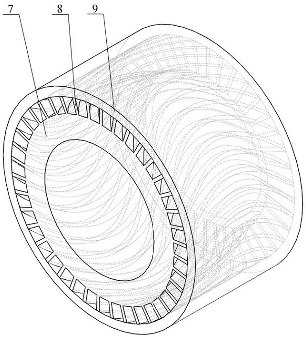
[0020] figure 2 A schematic diagram of the structure of an axial wave rotor that is bent and expanded gradually is shown. In the figure, the structure of this axial wave rotor that is bent and expanded mainly includes an inner shell 7, a baffle 8 and an outer shell 9. The inner shell 7 , The partition plate 8 and the outer shell 9 form 40 uniformly distributed back-bending and gradually expanding pressure oscillation tubes in the circumferential direction. The shape of the pressure oscillation tubes is a Bezier curve, the cross-sectional area gradually increases from the inlet to the outlet, and the appearance presents a back-bending. Expanding shape. where P 1 P 2 with P 1 P 4 Included angle θ 1 is 30 degrees, P 4 P 3 with P 4 P 1 Included angle θ 2 is 30 degrees; the cross-sectional area of ​​the rear end is twice that of the front end. The connecting line P between the two ends of the axis of the back-bend gradually expanding pressure oscillation tube 1 P 4 Th...

Embodiment 2

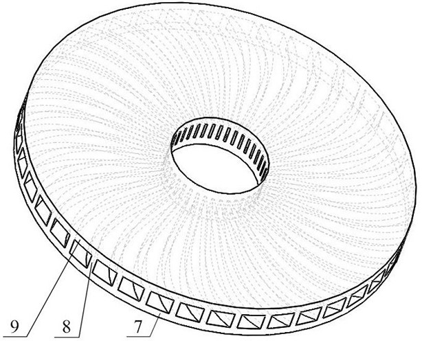
[0022] image 3 A schematic diagram of the structure of a radial wave rotor with back-bending and gradually expanding is shown. In the figure, the radial wave rotor structure of this kind of bending and expanding radial wave rotor mainly includes an inner shell 7, a partition plate 8 and an outer shell 9, and the inner shell 7, the baffle plate 8 and the outer shell 9 form 40 evenly distributed return bending gradually in the circumferential direction. Diffusion pressure oscillating tube, the shape of the pressure oscillating tube is a Bezier curve, the cross-sectional area gradually increases from the inlet to the outlet, and the appearance presents a back-bending and gradually expanding shape. Among them, P 1 P 2 with P 1 P 4 Included angle θ 1 is 0 degrees, P4 P 3 with P 4 P 1 Included angle θ 2 is 30 degrees; the cross-sectional area of ​​the rear end is 10 times that of the front end. The connecting line P between the two ends of the axis of the back-bend gradua...


PUM


Abstract

The utility model relates to a back-bending and gradually expanding refrigeration wave rotor capable of outputting shaft work, belonging to the field of gas expansion refrigeration. The main feature of this kind of refrigerating wave rotor that can output shaft work is the use of back-bending and gradually expanding pressure oscillation tubes. The curve shape of the axis of the pressure oscillation tube is described by a Bezier curve with 4 control points. It only needs to change the position of a few control points to achieve a complex curve shape, which effectively reduces the design variables and facilitates structural optimization. This type of oscillating tube has a small curvature in the front part and a large curvature in the back part, and the small curvature part can ensure a small jet loss, so that the gas wave expansion process runs stably and efficiently; The output shaft work further enriches the transformation method of the expansion work of the wave rotor and improves the adaptability of the wave rotor to the working conditions. The gradual expansion of the oscillating tube can realize the combination of gas wave expansion and volume expansion, thereby further improving the degree of expansion and refrigeration of the wave rotor, reducing the temperature of the gas after expansion, thereby improving the refrigeration efficiency.

Description

technical field [0001] The invention relates to a back-bending gradually expanding refrigeration wave rotor capable of outputting shaft work, and belongs to the field of gas expansion refrigeration. Background technique [0002] The wave rotor is a device that realizes the energy exchange of different pressure gases, and is currently widely used in the field of gas wave expansion refrigeration. Pressure oscillating tubes are distributed on the wave rotor, and the unsteady motion of shock waves and expansion waves in the pressure oscillating tubes realizes the transmission and conversion of energy between gases with different pressures, thereby achieving the purpose of refrigeration. [0003] At present, the field of gas wave expansion refrigeration has developed an external circulation dissipative pressure oscillating tube refrigeration method that outputs the expansion work in the form of heat energy, and a self-pressurized pressure oscillating tube refrigeration method tha...

Claims


Application Information

Patent Timeline
Patent Type & Authority Patents(China)
IPC IPC(8): F25B9/00F25B9/08
CPCF25B9/00F25B9/08
Inventor 刘培启胡大鹏刘新宇王海涛于洋王泽武范海贵阎琨
Owner DALIAN UNIV OF TECH
Why Eureka
Try Eureka