
Differential locking mechanism test method and rack

A technology of differential lock and test bench, which is applied in the testing of machine/structural parts, testing of mechanical parts, instruments, etc. It can solve the problems of high requirements for testers, inability to simulate the actual situation of the whole vehicle, and high cost

Active Publication Date: 2021-09-14
东风汽车零部件集团有限公司刃量具分公司
View PDF6 Cites 1 Cited by
  • Summary
  • Abstract
  • Description
  • Claims
  • Application Information

AI Technical Summary

Problems solved by technology

Among them, in the static shift test, there will always be a situation where the spline of the sliding gear sleeve and the tooth top of the locking spline face the tooth groove (such as Figure 4 ), it is impossible to simulate the actual situation of the whole vehicle, and the test results are not credible; the dynamic test of the bench can only use the traditional fatigue durable bench (one driving end, two loading ends), the test is cumbersome, the cost is high, and the requirements for testers are high. There is a lot of waste of bench resources; special road tests are carried out on the whole vehicle, the test cycle is long, and more manpower, material and financial resources are required
Whether it is a traditional bench dynamic test or a vehicle road test, there are defects such as cumbersome testing, large investment in testing resources, and high costs.

Method used


Image

  • Differential locking mechanism test method and rack
  • Differential locking mechanism test method and rack
  • Differential locking mechanism test method and rack

Examples


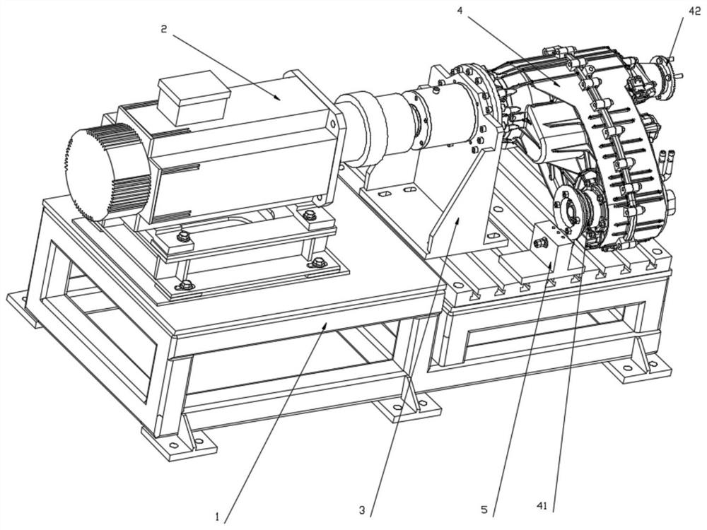
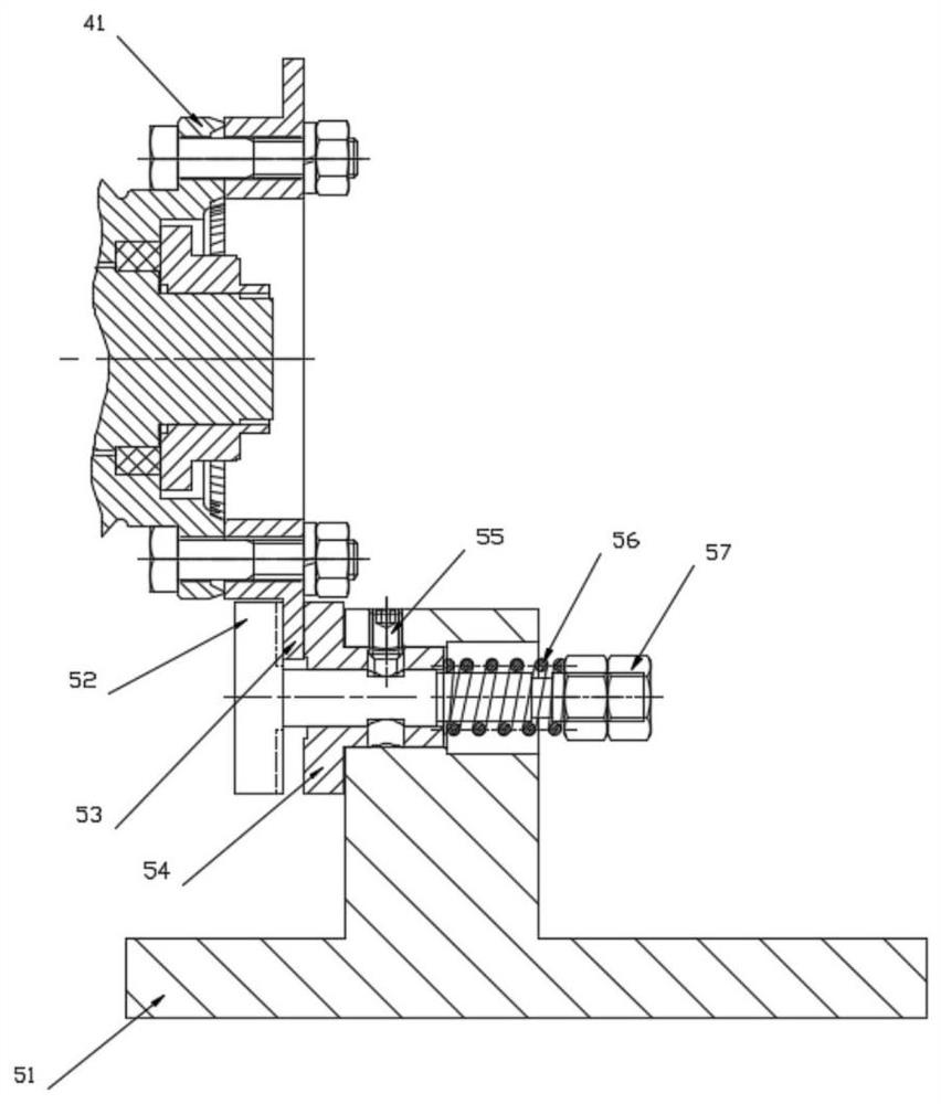
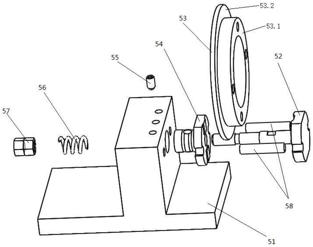
Embodiment Construction

[0028] The technical solution (including the preferred technical solution) of the present invention will be further described in detail below by means of the accompanying drawings and listing some optional embodiments of the present invention. Apparently, the described embodiments are only some of the embodiments of the present invention, not all of them. Based on the embodiments of the present invention, all other embodiments obtained by persons of ordinary skill in the art without creative efforts fall within the protection scope of the present invention.

[0029] The invention discloses a test method for a differential lock mechanism, which can ensure that the splines of the sliding gear sleeves and the splines of the locking splines correspond randomly to the tooth grooves of the differential product to be tested; When the differential product is driven by external force to rotate at low speed and the differential product to be tested is not locked, ensure that one output ...


PUM


Abstract

The invention discloses a differential locking mechanism test method and rack, which can ensure that tooth crests and tooth grooves of a sliding gear sleeve spline and a locking spline of a differential product to be tested randomly correspond in the detection process; when the differential product to be tested is driven by external force to rotate at a low speed and is not locked, one output end of the differential product does not rotate, and the other output end of the differential product freely rotates; when the differential product to be tested is driven by external force to rotate at a low speed and is subjected to differential locking, one output end and the other output end of the differential product rotate synchronously; and the differential product to be tested is controlled to be circularly switched between the unlocked state and the differential locking state of the differential product for multiple times, and whether the abrasion loss of the locking spline and a control mechanism of the differential product is qualified or not is verified. According to the invention, the phenomenon of asynchronous rotation of the input shaft and the output shaft caused by differential motion caused by road surfaces or vehicle tires during vehicle driving can be truly simulated, the purpose of simulating the state of the differential locking mechanism of the vehicle is achieved, and the test result is more real and credible.

Description

technical field [0001] The invention discloses a differential gear locking mechanism detection method and a test bench, which belong to the technical field of differential gear detection, and specifically discloses a differential gear locking mechanism testing method. Background technique [0002] Off-road vehicles and heavy trucks with poor road conditions are often equipped with a differential lock mechanism in the power transmission assembly with a differential function such as the transfer case or the middle axle or the front and rear axles in order to pursue the ability to get out of trouble and the ability to drive on low-adhesion roads. The function of the speed lock mechanism is to make the two output ends of the differential have the same speed (differential lock), so that the car can get out of trouble or run normally on low-adhesion roads. [0003] The differential lock connects the input of the differential with one of the outputs through the sliding gear sleeve ...

Claims


Application Information

Patent Timeline
Patent Type & Authority Applications(China)
IPC IPC(8): G01M13/025G01M13/00
CPCG01M13/025G01M13/00
Inventor 舒旭沈永平陈琦吴永亮聂晨晖
Owner 东风汽车零部件集团有限公司刃量具分公司
Learn More