Optical lens, camera module and electronic equipment

An optical lens and camera module technology, which is applied in the field of optical imaging, can solve the problems that the imaging quality of the optical lens is not clear enough, it is difficult to meet the high-definition imaging requirements of the optical lens, and the image quality of the optical lens is poor.

Active Publication Date: 2021-09-14
JIANGXI JINGCHAO OPTICAL CO LTD
View PDF16 Cites 4 Cited by
  • Summary
  • Abstract
  • Description
  • Claims
  • Application Information

AI Technical Summary

Problems solved by technology

In related technologies, under the trend of meeting the design trend of light, thin and miniaturized optical lenses, the image quality of optical lenses is poor, the re

Method used


Image

  • Optical lens, camera module and electronic equipment
  • Optical lens, camera module and electronic equipment
  • Optical lens, camera module and electronic equipment

Examples


no. 1 example

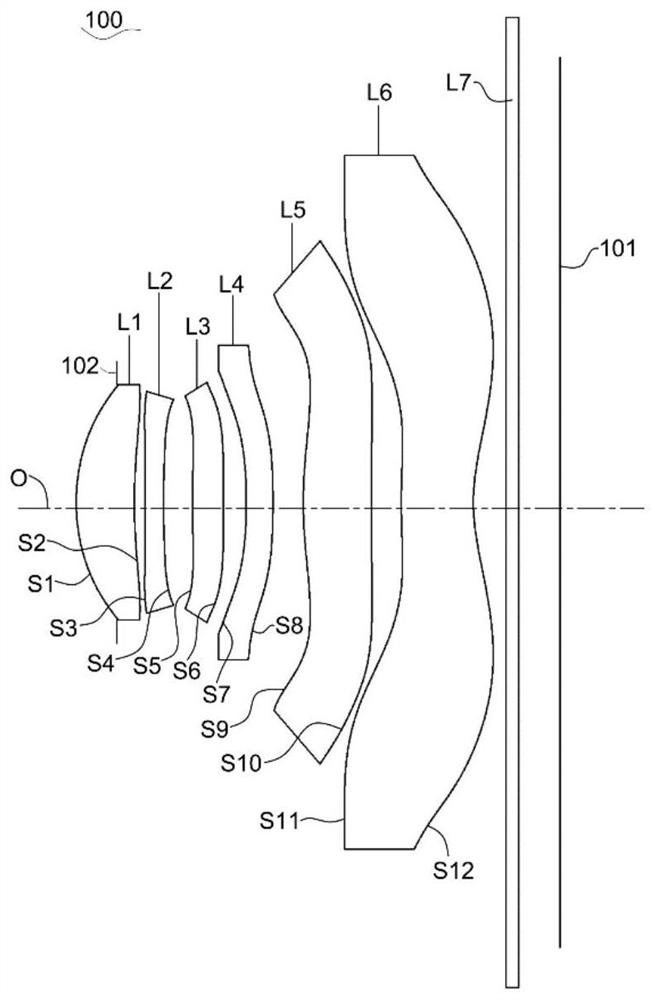
[0091] The optical lens structure of the first embodiment 100 of the present disclosure such as application of a schematic figure 1 , The first optical lens 100 includes a lens L1 along the optical axis O from the object side to the image side are arranged in order, a second lens L2, a diaphragm 102, a third lens L3, a fourth lens L4, the fifth lens L5 of, first filters and six lens L6 L7. Wherein, for the first lens L1, second lens L2, third lens L3, a fourth lens L4, the fifth lens L5 and the sixth lens L6 of a material can be found in the above-described specific embodiments is not repeated here.

[0092] Further, the first lens L1 having a positive refractive power, a second lens L2 having negative refractive power, a third lens L3 having a positive refractive power, a fourth lens L4 having a negative refractive power, the fifth lens L5 having a positive refractive power, a sixth lens L6 having a negative refractive power.

[0093] Still further, the object side surface of the...

no. 2 example

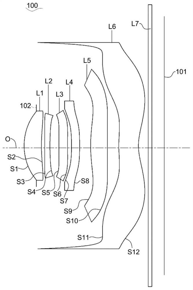
[0108] Please refer to image 3 , image 3 Schematic structural diagram of a second optical lens 100 of the embodiment of the present application. The optical lens 100 includes a first lens L1 along the optical axis O from the object side to the image side are arranged in order, a second lens L2, a diaphragm 102, a third lens L3, a fourth lens L4, the fifth lens L5 of, the sixth lens L6 and filter L7. Wherein, for the first lens L1, second lens L2, third lens L3, a fourth lens L4, the fifth lens L5 and the sixth lens L6 of a material can be found in the above-described specific embodiments is not repeated here.

[0109] Further, in the second embodiment, the refractive power of each lens and the refractive power differs from the first embodiment in that each lens of embodiment: a third lens L3 having negative refractive power. Meanwhile, in the second embodiment, the difference between the face surface model type each lens in the first embodiment in that each lens: the object side s...

no. 3 example

[0121] Please refer to Figure 5 , Figure 5 Shows a third embodiment of an optical lens of the present application structure diagram 100. The optical lens 100 includes a first lens L1 along the optical axis O from the object side to the image side are arranged in order, a second lens L2, a diaphragm 102, a third lens L3, a fourth lens L4, the fifth lens L5 of, the sixth lens L6 and filter L7. Wherein, for the first lens L1, second lens L2, third lens L3, a fourth lens L4, the fifth lens L5 and the sixth lens L6 of a material can be found in the above-described specific embodiments is not repeated here.

[0122] Further, in the third embodiment, the difference between the refractive power of the refractive power of each lens of the first embodiment in that each lens: a fourth lens L4 having positive refractive power. Meanwhile, in the third embodiment, the difference between the face surface model type each lens in the first embodiment in that each lens: the object side surface of t...


PUM

PropertyMeasurementUnit
Optical lengthaaaaaaaaaa

Abstract

The invention discloses an optical lens, a camera module and electronic equipment. The optical lens comprises a first lens element, a second lens element, a third lens element, a fourth lens element, a fifth lens element and a sixth lens element which are sequentially arranged from an object side to an image side along an optical axis. The first lens element with positive refractive power has a convex object-side surface and a concave image-side surface, respectively. The second lens element with negative refractive power has a convex object-side surface and a concave image-side surface, respectively. The sixth lens element with negative refractive power has a concave image-side surface. The optical lens satisfies the following relation: 1.3 mm < Imh^2/TTL/Fno < 1.42 mm, wherein TTL is the distance from the object-side surface of the first lens to the imaging surface of the optical lens on the optical axis, Imgh is half of the length of a diagonal line of an effective pixel area on the imaging surface of the optical lens, and Fno is the number of apertures of the optical lens. According to the optical lens, the camera module and the electronic equipment provided by the invention, the picture quality of the optical lens can be improved while the optical lens is designed to be light, thin and miniaturized, and the resolution and the imaging definition of the optical lens are improved.

Description

Technical field [0001] The present invention relates to a technical field of optical imaging and more particularly relates to an optical lens, a camera module and an electronic apparatus. Background technique [0002] Now, with the development of camera technology, people increasingly high image quality optical lens requirements, and light structural characteristics of miniaturization is becoming the development trend of optical lens. In the related art, in the light satisfying the optical lens design trends of miniaturization, the optical lens poor quality sense, lower resolution, and image quality of the optical lens is also not clear enough, it is difficult to meet the requirements of high-definition imaging optical lens . Inventive content [0003] Example discloses an optical lens, a camera module and an electronic apparatus according to the present invention, while achieving a thin optical lens, compact design, the optical lens to improve image quality sense, increasing th...

Claims


Application Information

Patent Timeline
IPC IPC(8): G02B13/00G02B13/14G02B13/18H04N5/225
CPCG02B13/0045G02B13/008G03B30/00H04N23/55
Inventor 徐标李明
Owner JIANGXI JINGCHAO OPTICAL CO LTD
Why Eureka
Try Eureka