
Wireless charging type mobile phone mobile power supply

A mobile phone mobile and wireless charging technology, which is applied to electric vehicles, battery circuit devices, current collectors, etc., can solve the problems of mobile phone wireless mobile power damage, mobile phone falling, and inconvenient use for users

Pending Publication Date: 2021-09-14
刘慧磊
View PDF1 Cites 0 Cited by
  • Summary
  • Abstract
  • Description
  • Claims
  • Application Information

AI Technical Summary

Problems solved by technology

[0004] In order to make up for the deficiencies of the existing technology, when the wireless mobile power supply is charging the mobile phone, it is necessary to place the wireless mobile power supply horizontally, and then place the mobile phone horizontally on the wireless mobile power supply. When the user needs to use the mobile phone to watch movies, browse When browsing the webpage, the user’s eyes are required to look directly at the mobile phone screen, which is inconvenient for the user to use, and in the process of walking, the user is inconvenient to carry the wireless mobile power supply that is charging the mobile phone, and the mobile phone is easy to fall from the wireless mobile power supply, causing The problem of damage to mobile phones or wireless mobile power supplies, a wireless charging mobile phone mobile power supply proposed by the present invention

Method used


Image

  • Wireless charging type mobile phone mobile power supply
  • Wireless charging type mobile phone mobile power supply
  • Wireless charging type mobile phone mobile power supply

Examples


Embodiment approach

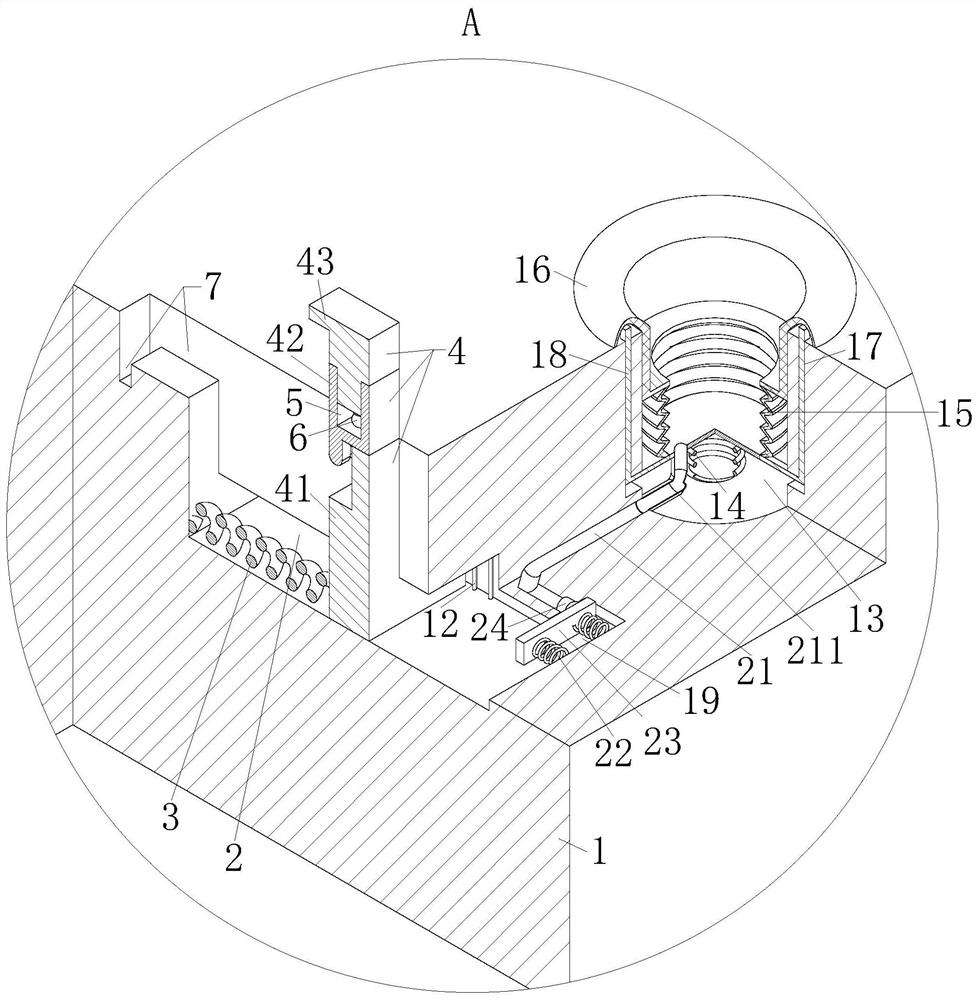
[0033] As an embodiment of the present invention, the rotating rod 42 and the clamping rod 43 are evenly fixed with a plurality of rubber blocks 11 on the surface close to the first spring 3; the clamping rod 43 is on the lower surface in the horizontal direction A plurality of rubber blocks 11 are evenly fixed;

[0034] During work, after the mobile phone is clamped by the bracket 4, the rotating rod 42 and the clamping rod 43 are evenly fixed on a plurality of rubber blocks 11 near the surface of the first spring 3, which can increase the size of the mobile phone side wall and the rotating rod 42 and clamping. The friction between the holding rods 43 effectively prevents the mobile phone from sliding and prevents the mobile phone from falling. The multiple rubber blocks 11 evenly fixed on the lower surface of the clamping rod 43 in the horizontal part can increase the use surface of the mobile phone and the clamping rod 43 The friction force between them, and prevent the cla...


PUM


Abstract

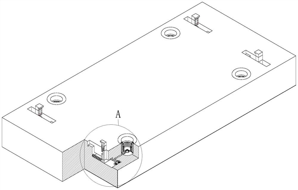
The invention belongs to the field of wireless mobile power sources, and particularly relates to a wireless charging type mobile phone mobile power supply. The mobile power supply comprises a shell; first sliding grooves are formed in the shell; the first sliding grooves are symmetrically distributed along the center line in the length direction of the shell; the cross section of each first sliding groove is in a T shape, and the upper portion of each first sliding groove penetrates through the upper surface of the shell; a support is elastically connected into each first sliding groove through a first spring; a groove is formed in the upper part of the shell; a first circular groove is formed in the shell, and a coil is fixedly connected in the first circular groove; and the coil is electrically connected with a power supply in the shell. The mobile power supply is simple in structure, the angle of the wireless mobile power supply can be adjusted when the wireless mobile power supply charges a mobile phone, a user can use the wireless mobile power supply conveniently, and the problems that in the walking process, the user inconveniently carries the wireless mobile power supply which is charging the mobile phone, the mobile phone is prone to falling off from the wireless mobile power supply, and the mobile phone or the wireless mobile power supply is damaged can be solved.

Description

technical field [0001] The invention belongs to the field of wireless mobile power supplies, in particular to a wireless charging mobile phone mobile power supply. Background technique [0002] Wireless charging is mainly achieved through the following three methods: electromagnetic induction, radio waves, and electromagnetic resonance. The most common wireless charging solution is: electromagnetic induction, which induces current through the primary and secondary coils, thereby transferring energy from the transmission section to the receiving end. However, when the wireless mobile power supply is charging the mobile phone, the wireless mobile power supply needs to be placed horizontally, and then the mobile phone is placed horizontally on the wireless mobile power supply. When the user needs to use the mobile phone to watch movies or browse the web, the user needs to face up Due to the screen of the mobile phone, it is inconvenient for the user to use, and in the process ...

Claims


Application Information

Patent Timeline
IPC IPC(8): H02J7/00H02J50/00
CPCH02J7/0044H02J50/005
Inventor 刘慧磊张辰星
Owner 刘慧磊
Learn More