An anti-rotation orthopedic internal fixator

An internal fixation, anti-rotation technology, applied in the field of medical devices, can solve the problems of damage to the blood supply of the femoral head, large trauma, and damage to the blood supply, and achieve the effects of avoiding ischemic necrosis, avoiding trauma, and avoiding blood supply.

Active Publication Date: 2022-05-13
王欣欣
View PDF9 Cites 0 Cited by
  • Summary
  • Abstract
  • Description
  • Claims
  • Application Information

AI Technical Summary

Problems solved by technology

[0002] At present, avulsion fractures, diaphysis fractures, and femoral neck fractures often occur clinically. For avulsion fractures, screws or Kirschner wires are often used for clinical fixation. If a single Kirschner wire has no anti-rotation ability, it is prone to rotational displacement of the fracture end after surgery
If multiple Kirschner wires will cause more wounds than a single one, the anti-rotation ability of two Kirschner wires is poor. According to mathematical theory, because three points fix a plane, three Kirschner wires can be fixed stably, but the wound is obviously weaker. The single root is large, and there may be a risk of destroying blood supply; when the existing products are fixed in the bone marrow, there are many incisions, and the locking nails at both ends cause new soft tissue and bone trauma; when the existing products are used to fix femoral neck fractures, The traditional three hollow nails are more traumatic than a single internal fixation, and destroy the blood supply of the femoral head, which is likely to cause femoral head necrosis
In recent years, a single internal fixation has poor anti-rotation ability, which may easily cause the rotation and displacement of the fracture end, resulting in nonunion or severe malunion

Method used


Image

  • An anti-rotation orthopedic internal fixator
  • An anti-rotation orthopedic internal fixator
  • An anti-rotation orthopedic internal fixator

Examples


Embodiment 1

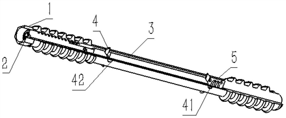
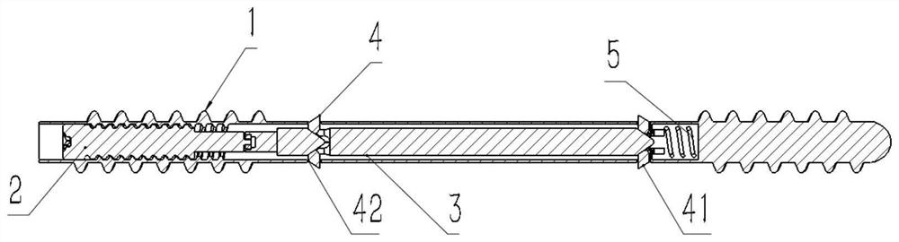
[0050] like Figure 1-2As shown, it is an anti-rotation orthopedic internal fixation device of the present invention, which includes an outer sleeve 1, a positioning assembly 4, an operating assembly for controlling the movement of the positioning assembly 4, and a return spring 5; the operating assembly includes a proximal push rod 223 and The distal sliding rod 3; the proximal push rod 223 is arranged inside the outer sleeve 1 and is slidably connected with the outer sleeve 1; the distal sliding rod 3 is arranged inside the outer sleeve 1 and is located inside the proximal push rod 223 , the distal slide bar 3 is slidably connected with the outer sleeve 1; the positioning components 4 are respectively arranged at both ends of the distal slide bar 3, and are detachably connected with the distal slide bar 3; one end of the return spring 5 is connected to the distal end The end of the slide rod 3 away from the mouth of the threaded pipe 11 is integrally connected, and the other...

Embodiment 2

[0056] like Figure 3-9 As shown, the following specific settings are carried out on the basis of embodiment 1 for this embodiment:

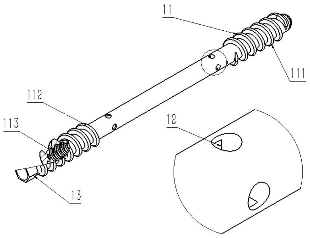
[0057] The threaded tube 11 is a tubular structure with round holes on the side walls at both ends. The outer two ends are respectively provided with a distal thread 111 and a proximal thread 112 for fixing the whole body in the patient's body. The inner opening is provided with a proximal push rod. 223 to match the internal thread 113.

[0058] The distal guide structure 12 is an arc-shaped plate structure; the distal guide structure 12 is arranged inside the round hole of the outer tube 1 away from the nozzle end, and is integrally connected with the outer tube 1 .

[0059] The tightening structure is a hexagonal prism structure with a cylindrical through hole in the center, which is arranged at the nozzle of the outer casing 1 and integrally connected with the outer casing 1 .

[0060] The stud 21 is a cylindrical structure with threads on ...

Embodiment 3

[0070] like Figure 10-13 As shown, the difference between this embodiment and embodiment 2 is:

[0071] Both sides of the threaded tube 11 are respectively provided with round holes, and the inner sides of the round holes are respectively provided with inclined surfaces for assisting the entry and exit of the distal positioning structure 41 and the proximal positioning structure 42 .

[0072] The rod body 31 is a rectangular columnar structure; the distal slideway 322 includes a distal I-shaped slideway 3221 ; the proximal slideway 332 includes a proximal I-shaped slideway 3321 .

[0073] The far-end I-shaped slideway 3221 is a T-shaped structure, which is arranged on the central axis of the distal inclined surface 321, and is integrally connected with the distal-end inclined surface 321; the proximal-end I-shaped slideway 3321 is a T-shaped structure, which is arranged on the on the central axis of the proximal bevel 331 and integrally connected with the proximal bevel 331 ...


PUM


Abstract

The invention discloses an anti-rotation orthopedic internal fixer, which comprises an outer sleeve, a positioning assembly, an operating assembly for controlling the movement of the positioning assembly, and a return spring; the operating assembly includes a proximal push rod and a distal slide rod; the proximal push rod is set It is inside the outer casing and is slidingly connected with the outer casing; the distal sliding rod is arranged inside the outer casing, and is located on the inner side of the proximal push rod, and the distal sliding rod is slidingly connected with the outer casing; the positioning components are respectively arranged on the two sides of the distal sliding rod One end is detachably connected with the far-end slide rod; one end of the return spring is integrally connected with the nozzle end of the far-end slide rod away from the threaded pipe, and the other end is integrally connected with the inner bottom of the threaded pipe. This design has anti-rotation and avoids trauma caused by multiple internal fixation objects. At the same time, it can well protect the blood supply of the fracture end, avoid destroying the blood supply of the fracture end and the non-fracture site, and avoid avascular necrosis in some parts. It is very important for avulsion fractures, diaphysis fractures, and femoral neck fractures.

Description

technical field [0001] The invention belongs to the technical field of medical devices, and in particular relates to an anti-rotation orthopedic internal fixator. Background technique [0002] At present, avulsion fractures, diaphysis fractures, and femoral neck fractures often occur clinically. For avulsion fractures, screws or Kirschner wires are often used for clinical fixation. If a single Kirschner wire has no anti-rotation ability, it is prone to rotational displacement of the fracture end after operation. If multiple Kirschner wires will cause more wounds than a single one, the anti-rotation ability of two Kirschner wires is poor. According to mathematical theory, because three points fix a plane, three Kirschner wires can be fixed stably, but the wound is obviously weaker. The single root is large, and there may be a risk of destroying blood supply; when the existing products are fixed in the bone marrow, there are many incisions, and the locking nails at both ends ...

Claims


Application Information

Patent Timeline
Patent Type & Authority Patents(China)
IPC IPC(8): A61B17/68A61B17/74A61B17/86
CPCA61B17/68A61B17/86A61B17/74A61B17/8605A61B2017/8655
Inventor 郝瑞胡王欣欣郭林
Owner 王欣欣
Why Eureka
Try Eureka