Branch cutting device for bioengineering
A cutting device and bioengineering technology, which is applied in the direction of sampling device, plant material machining, mechanical equipment, etc., can solve the problems of inconsistent branch length, effort, affecting branch processing, etc., and achieve the effect of consistent length
- Summary
- Abstract
- Description
- Claims
- Application Information
AI Technical Summary
Problems solved by technology
Method used
Image
Examples
Embodiment 1
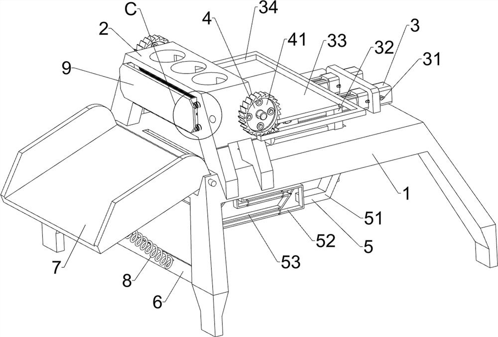
[0025] A branch cutting device for bioengineering, such as figure 1 and figure 2 As shown, it includes a support seat 1, a three-hole seat 2, a cutting mechanism 3 and a conveying mechanism 4. The upper part of the support seat 1 is provided with a cutting mechanism 3, and a three-hole seat 2 is fixedly connected between the front and rear parts on the left side of the outer top of the support seat 1. , The right part of the three-hole seat 2 is provided with a conveying mechanism 4, and the conveying mechanism 4 contacts and cooperates with the cutting mechanism 3.
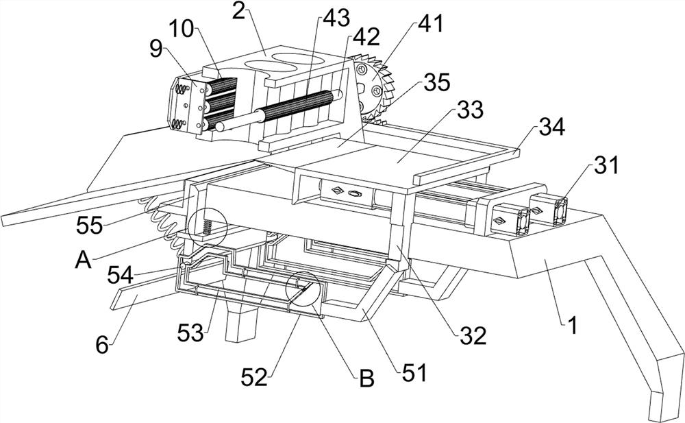
[0026] The cutting mechanism 3 includes a cylinder 31, a guide block 32, an L-shaped plate 33, a U-shaped ratchet bar 34 and a cutter 35. The front and rear sides of the support base 1 are slidably connected with the guide block 32, and the front and rear sides of the guide block 32 tops are fixedly connected with an L-shaped plate 33, the bottom end of the L-shaped plate 33 contacts and cooperates with the out...
Embodiment 2
[0032] On the basis of Example 1, such as Figure 1-Figure 4As shown, it also includes a stopper mechanism 5, and the stopper mechanism 5 includes an L-shaped block 51, a special-shaped frame 52, a special-shaped guide frame 53, a guide shaft 54, a baffle plate 55, a first spring 56, a u-shaped bar 57, a swing Rod 58 and torsion spring 59, guide block 32 bottom ends are affixed with L-shaped block 51, and L-shaped block 51 left ends are affixed with special-shaped frame 52, front side special-shaped frame 52 front side circumferential direction and rear side special-shaped frame 52 rear side circumferences. Four u-shaped bars 57 are fixedly connected to each side, and special-shaped guide frames 53 are fixedly connected between the inner ends of all u-shaped bars 57 on each side. The special-shaped guide frames 53 are positioned in the special-shaped frame 52. A swing rod 58 is connected, and a torsion spring 59 is connected to the joint between the swing rod 58 and the specia...
Embodiment 3
[0035] On the basis of embodiment 1 and embodiment 2, such as figure 1 , figure 2 and Figure 5 As shown, it also includes a fixed plate 6, a swing frame 7 and a second spring 8, the fixed plate 6 is fixedly connected between the lower parts of the front and rear sides of the left part of the support base 1, and the left side of the outer top of the support base 1 is connected with a swing Frame 7, a second spring 8 is symmetrically connected between the left side of the outer bottom of the swing frame 7 and the left side of the fixed plate 6 .
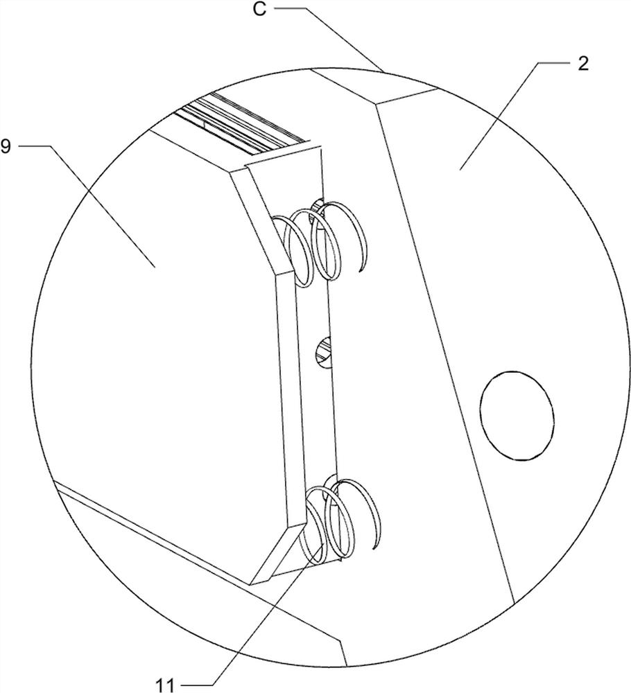
[0036] Also comprise u-shaped plate 9, guide roller 10 and the 3rd spring 11, the sliding type embedded in the middle of the upper part of the left side of three-hole seat 2 is provided with u-shaped plate 9, the front and rear sides of the left side in the u-shaped plate 9 are respectively connected with There is a third spring 11 symmetrically connected between the front and rear sides of the left side of the three-hole seat 2, a...
PUM
 Abstract
Description
Claims
Application Information
 - R&D
- Intellectual Property
- Life Sciences
- Materials
- Tech Scout
- Unparalleled Data Quality
- Higher Quality Content
- 60% Fewer Hallucinations
Browse by: Latest US Patents, China's latest patents, Technical Efficacy Thesaurus, Application Domain, Technology Topic, Popular Technical Reports.
© 2025 PatSnap. All rights reserved.Legal|Privacy policy|Modern Slavery Act Transparency Statement|Sitemap|About US| Contact US: help@patsnap.com


