
Extruder device for automatically controlling and adjusting extrusion amount in rubber injection molding screw

A technology of extrusion volume and extruder, which is applied in the field of extruder device for automatic control and adjustment of extrusion volume, which can solve problems such as unstable cross-sectional area of ​​products, poor adaptability to different rubbers, failure of vacuuming, etc. The effects of precise movement, avoidance of vacuum failure, and precise flow control

Pending Publication Date: 2021-09-17
浙江百纳橡塑设备有限公司
View PDF2 Cites 0 Cited by
  • Summary
  • Abstract
  • Description
  • Claims
  • Application Information

AI Technical Summary

Problems solved by technology

[0003] However, in the actual production process, it was found that the cross-sectional area of ​​the exhaust ring and the steel sleeve of the fuselage was fixed, resulting in poor adaptability of the equipment to different rubbers.
Due to the variety of rubber varieties and specifications, the Mooney viscosity, hardness, and extrusion performance all have obvious differences. However, the cross-sectional area between the screw exhaust ring and the rigid sleeve in the original design is fixed and consistent, which cannot adapt to the extrusion of different rubbers. Under the condition of constant pressure, the amount of raw materials with good extrusion performance and good fluidity passing through the exhaust ring is large, and vice versa. If there is too much, the raw material will come out from the vacuum port, resulting in vacuum failure
And if there is too little from the exhaust ring, it will cause the screw groove of the extrusion section to lack glue, which will affect the instability of the cross-sectional area of ​​the product.

Method used


Image

  • Extruder device for automatically controlling and adjusting extrusion amount in rubber injection molding screw
  • Extruder device for automatically controlling and adjusting extrusion amount in rubber injection molding screw
  • Extruder device for automatically controlling and adjusting extrusion amount in rubber injection molding screw

Examples


Embodiment Construction

[0028] In order to facilitate the understanding of the technical solution of the present invention, the following describes in detail in conjunction with the accompanying drawings and specific embodiments.

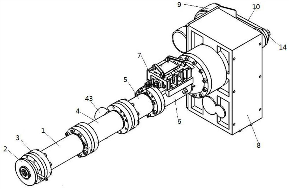
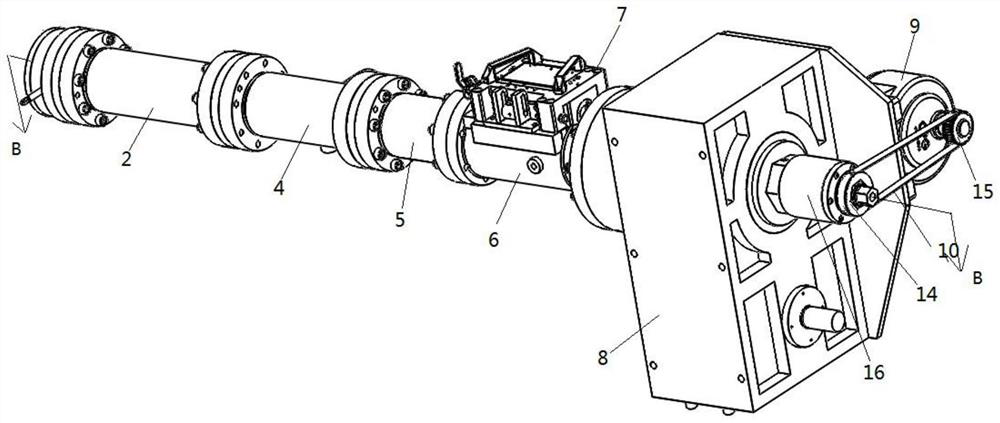
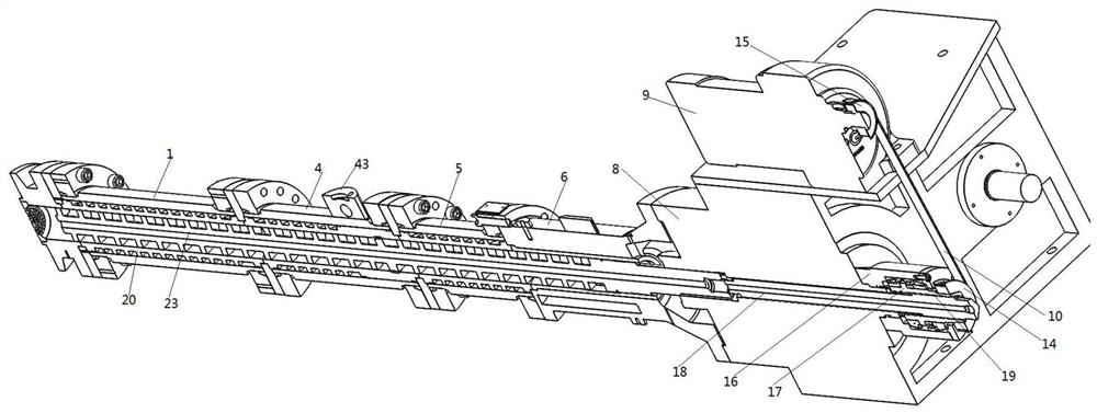
[0029] see Figure 1-10 , an extruder device for automatically controlling and adjusting the extrusion volume in a rubber injection molding screw, which includes a barrel and a speed reducer 8, and the barrel is fixedly connected to the output end of the speed reducer 8;

[0030] A steel sleeve 20 is sleeved in the barrel, a spiral channel is formed between the steel sleeve 20 and the barrel, a screw 23 is sleeved in the steel sleeve 20, and an exhaust ring is arranged on the screw 23 231, the maximum circumscribed circle of the exhaust ring 231 is greater than the diameter of the circumscribed circles at both ends, and an exhaust ring groove 201 matching the exhaust ring 231 is dug on the inner wall of the steel sleeve 20, the exhaust ring 231 The largest circumscribed c...


PUM


Abstract

The invention discloses an extruder device for automatically controlling and adjusting the extrusion amount in a rubber injection molding screw. The extruder device comprises a machine barrel and a speed reducer, wherein the machine barrel is fixedly connected to the output end of the speed reducer; a steel sleeve is connected in the machine barrel in a sleeving mode; a screw is connected in the steel sleeve in a sleeved mode; an exhaust ring is arranged on the screw; the maximum circumcircle of the exhaust ring is greater than the diameter of circumcircles at the two ends; an exhaust ring groove matched with the exhaust ring is formed in the inner wall of the steel sleeve; a screw adjusting device is arranged in the speed reducer; the screw adjusting device comprises a screw adjustable pull rod which penetrates through the speed reducer and is arranged in the speed reducer in a sliding connection mode; the output tail end of the pull rod abuts against the screw; and the output front end of the pull rod extends out of the speed reducer.

Description

technical field [0001] The invention relates to the technical field of rubber extruders, in particular to an extruder device for automatically controlling and adjusting the extrusion volume in a rubber injection molding screw. Background technique [0002] During the rubber extrusion molding process, in order to increase the product density, the rubber extruder is usually designed as a vacuum extruder. Therefore, the exhaust extruder body must be heatable and temperature controllable, and the screw must have a certain compression ratio and stirring capacity. The purpose is to plasticize the rubber quickly, and then design the screw as an exhaust ring, and use the exhaust groove ring to compress the plasticized rubber into thin sheets, so that the water vapor inside the rubber can be discharged and transported to the extrusion section, because extrusion The outlet section is in a relatively vacuum environment, and the discharged water vapor can be quickly vaporized in a rela...

Claims


Application Information

Patent Timeline
IPC IPC(8): B29C45/47B29C45/60B29C45/62B29C45/63B29C45/76
CPCB29C45/47B29C45/60B29C45/62B29C45/63B29C45/76B29C2945/76859
Inventor 姚央军徐荣国应再兴朱建国王均委
Owner 浙江百纳橡塑设备有限公司
Learn More