
Holographic radar three-dimensional imaging method and device based on TCSPC

A three-dimensional imaging and holographic technology, applied in the field of holographic imaging, can solve the problems of weak environmental perception ability of autonomous driving technology and insufficient collection of surrounding environment information, and achieve the effect of improving the ability

Inactive Publication Date: 2021-09-17
TSINGHUA UNIV
View PDF5 Cites 0 Cited by
  • Summary
  • Abstract
  • Description
  • Claims
  • Application Information

AI Technical Summary

Problems solved by technology

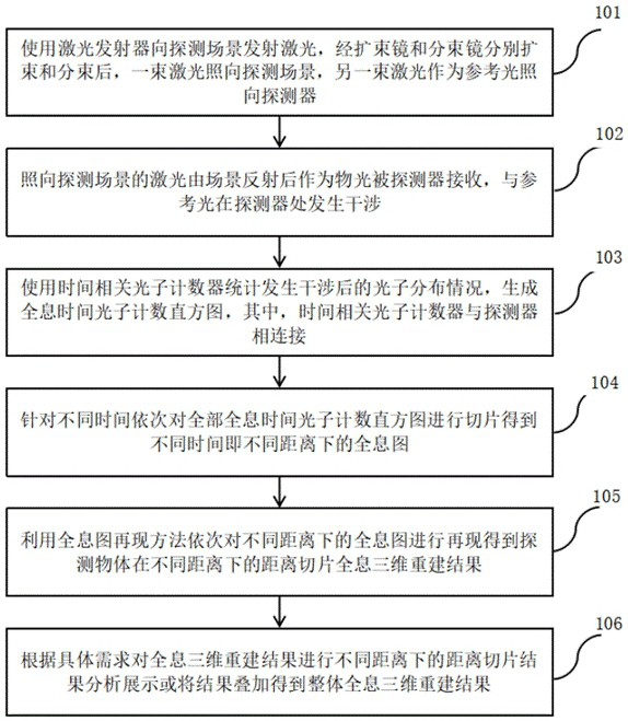
[0006] For this reason, the first purpose of this application is to propose a holographic radar three-dimensional imaging method based on TCSPC, which solves the problem that the existing method does not sufficiently collect the surrounding environment information, which leads to the weak environmental perception ability of automatic driving technology. Based on TCSPC Holographic 3D reconstruction of the detected object at different distances is carried out through holographic imaging. While ensuring high-precision depth information measurement, it can not only carry out holographic 3D reconstruction of distance slices at different distances for the object to be detected, but also obtain the overall holographic 3D of the object. The reconstruction results provide sufficient environmental three-dimensional data support for autonomous driving technology, improve the existing problems of environmental perception technology, and effectively improve the ability of autonomous driving technology to perceive the surrounding environment

Method used


Image

  • Holographic radar three-dimensional imaging method and device based on TCSPC
  • Holographic radar three-dimensional imaging method and device based on TCSPC
  • Holographic radar three-dimensional imaging method and device based on TCSPC

Examples


Embodiment Construction

[0025] Embodiments of the present application are described in detail below, examples of which are shown in the drawings, wherein the same or similar reference numerals denote the same or similar elements or elements having the same or similar functions throughout. The embodiments described below by referring to the figures are exemplary, and are intended to explain the present application, and should not be construed as limiting the present application.

[0026] The TCSPC-based holographic radar three-dimensional imaging method and device according to the embodiments of the present application will be described below with reference to the accompanying drawings.

[0027] figure 1 It is a flow chart of a TCSPC-based holographic radar three-dimensional imaging method provided in Embodiment 1 of the present application.

[0028] like figure 1 As shown, this TCSPC-based holographic radar three-dimensional imaging method comprises the following steps:

[0029] Step 101, using a ...


PUM


Abstract

The invention provides a TCSPC-based holographic radar three-dimensional imaging method and device; the method comprises the steps: transmitting laser to a detection scene, enabling one laser beam to irradiate the detection scene after beam expansion and beam splitting, and enabling the other laser beam to serve as reference light to irradiate a detector; reflecting the laser irradiated to the detection scene by the scene and then is received by the detector as object light, wherein the object light interferes with the reference light at the detector; counting the photon distribution condition after interference by using a time correlation photon counter to generate a holographic time photon counting histogram; sequentially slicing the holographic time photon counting histogram according to different time to obtain holograms at different distances; reappearing the holograms at different distances in sequence to obtain distance slice holographic three-dimensional reconstruction results of the detected object at different distances; and analyzing, displaying or superposing distance slice results under different distances according to specific requirements to obtain an overall holographic three-dimensional reconstruction result. According to the invention, high-precision information measurement is ensured, and the ability of the automatic driving technology to perceive the surrounding environment is improved.

Description

technical field [0001] The present application relates to the technical field of holographic imaging, and in particular to a TCSPC-based holographic radar three-dimensional imaging method and device. Background technique [0002] Holographic imaging technology is a technology that records three-dimensional information of objects and reproduces three-dimensional images of objects through the principles of light interference and diffraction. Holographic imaging technology is divided into two parts: the recording process and the reproduction process. During the recording process, the laser is emitted by the laser and split into beams. One beam illuminates the object, and the other beam illuminates the holographic recording surface as a reference beam. The laser beam that illuminates the object is reflected by the object and returns to the The holographic recording surface interferes with the reference light to form a hologram, and the interference fringes on the hologram record...

Claims


Application Information

Patent Timeline
Patent Type & Authority Applications(China)
IPC IPC(8): G01S17/89G01S17/931
CPCG01S17/89G01S17/931
Inventor 戴琼海邬京耀裴承全李鹏蔡宇麟
Owner TSINGHUA UNIV
Learn More