Finished product discharging equipment for automatic vehicle steering knuckle full-automatic press-fitting line
A steering knuckle, fully automatic technology, used in metal processing equipment, vehicle parts, transportation and packaging, etc., can solve the problems of inconvenient use and inconvenient adjustment of the angle of the conveying plate, and achieve the effect of improving stability and preventing tipping
- Summary
- Abstract
- Description
- Claims
- Application Information
AI Technical Summary
Problems solved by technology
Method used
Image

Examples
Embodiment 1
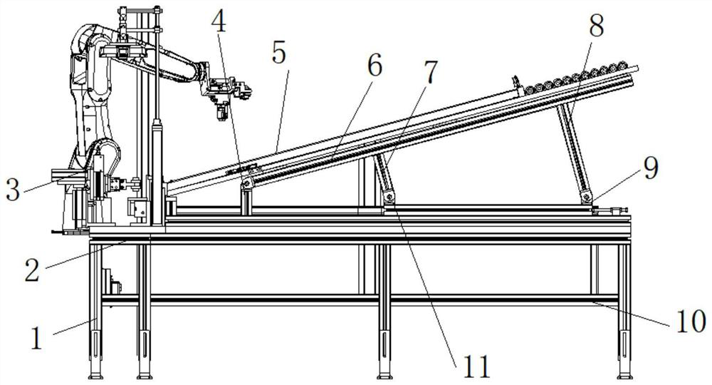
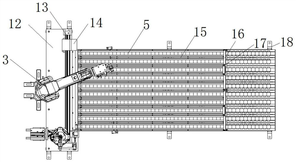
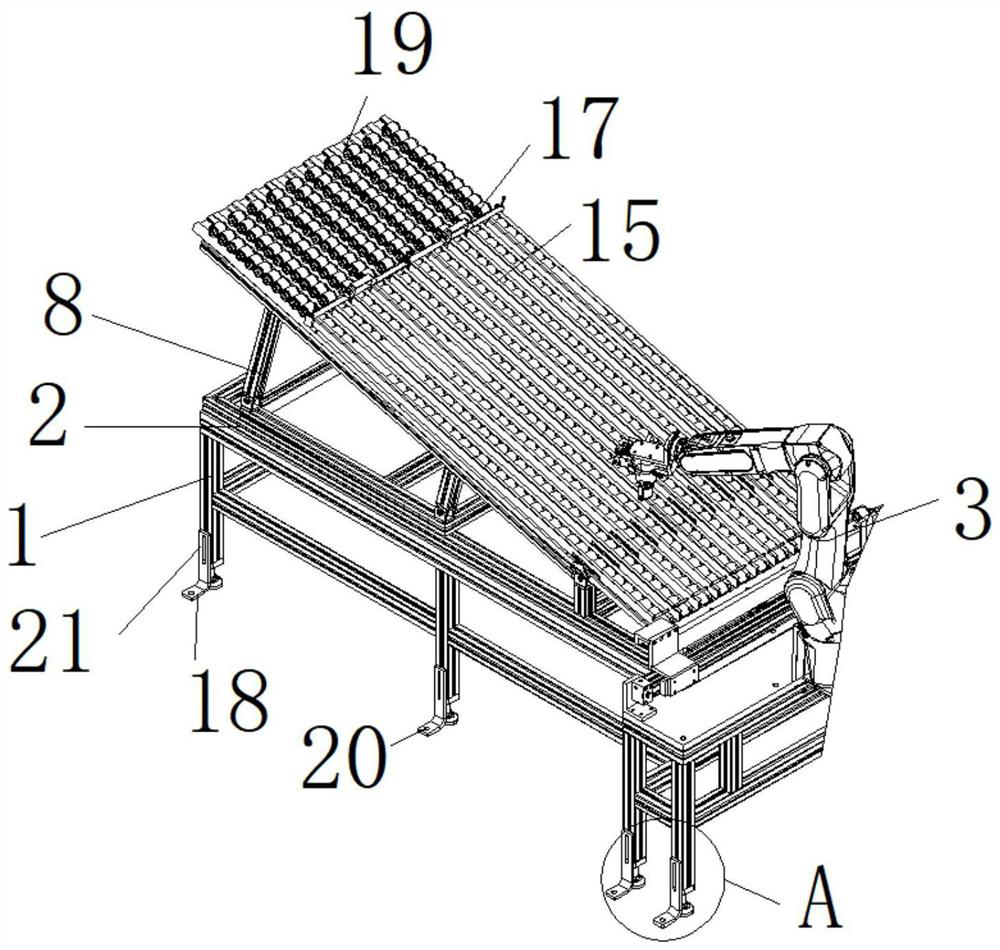
[0028] Example 1: See Figure 1-6 , a finished product discharge device for automatic car steering knuckle automatic press assembly line, including a first anti-skid foot 1 and a support frame 2, the bottom end of the support frame 2 is welded with the first anti-skid foot 1, and one side of the top of the support frame 2 Workbench 12 is installed, one side of the top of the workbench 12 is provided with a limit slide bar 13, the other side of the top of the workbench 12 is equipped with a clamping mechanical arm main body 3, and a connecting frame 10 is welded between the first anti-skid legs 1 The top of one side of the workbench 12 is hinged with a transmission plate 5, the top of the support frame 2 is provided with a guide bracket 6, the transmission plate 5 is connected with the guide bracket 6, and the outside of the limit slide bar 13 is sleeved with a sliding sleeve 14. The sleeve 14 is fixedly connected to one end on one side of the transmission plate 5;
[0029] se...
Embodiment 2
[0031] Embodiment 2: One side of the guide bracket 6 is provided with a connecting plate, the mounting plate 4 is articulated through the hinge block and the connecting plate, and the first electric push rod 7 is articulated between the guide bracket 6 and the second installation block 11 through the hinge block. , the second electric push rod 8 is flexibly hinged between the other side of the bottom end of the guide bracket 6 and the first installation block 9 through the hinge block;
[0032] Specifically, such as figure 1 and image 3As shown, since one side of the mounting plate 4 and the guide bracket 6 is hinged, so when the first electric push rod 7 and the second electric push rod 8 drive the other side of the guide bracket 6 to rise, one side of the guide bracket 6 will pass through The hinge block moves at the top of the mounting plate 4, and the first electric push rod 7 and the second electric push rod 8 can be set at the same time through the guide bracket 6 to i...
Embodiment 3
[0033] Embodiment 3: the other end on one side of the transmission plate 5 is provided with a drive motor 22, the output end of the drive motor 22 is fixedly connected with a drive gear 25 through a coupling, and the bottom end of the transmission plate 5 is provided with a conveyor belt main body 24, the conveyor belt main body The other side inside 24 is provided with driven gear 23, and the inside of driven gear 23 is provided with connecting shaft, and connecting shaft is movably connected with the other side inside transmission plate 5, and driving gear 25 is arranged on one side inside conveyor belt main body 24 , the driving gear 25 and the driven gear 23 are at the same level;
[0034] Specifically, such as Figure 4 As shown, start the driving motor 22 while placing the workpiece, and the driving motor 22 will drive the driving gear 25 to rotate through the shaft coupling. When the driving gear 25 rotates, the conveyor belt main body 24 outside the driving gear 25 wil...
PUM
 Abstract
Description
Claims
Application Information
 - R&D Engineer
- R&D Manager
- IP Professional
- Industry Leading Data Capabilities
- Powerful AI technology
- Patent DNA Extraction
Browse by: Latest US Patents, China's latest patents, Technical Efficacy Thesaurus, Application Domain, Technology Topic.
© 2024 PatSnap. All rights reserved.Legal|Privacy policy|Modern Slavery Act Transparency Statement|Sitemap