Special clamp for multi-surface milling and boring of large parts

A technology of large-scale parts and special fixtures, which is applied in the direction of metal processing machinery parts, clamping, manufacturing tools, etc., can solve the problems of complex and cumbersome processing procedures, low production efficiency, affecting production progress and economic benefits, and save auxiliary time , easy operation, small vibration effect

Pending Publication Date: 2021-09-24
QIQIHAR NORTH MACHINERY CORP
View PDF9 Cites 2 Cited by
  • Summary
  • Abstract
  • Description
  • Claims
  • Application Information

AI Technical Summary

Problems solved by technology

The processing plan of this part in the scientific research stage is to align and clamp on ordinary milling machines and ordinary boring machines, and process the grooves and holes on each surface separately. After the successful trial production, the product is now transferred to mass production, and the processing procedures are more complicated and cumbersome. The production efficiency is not high, which affects the production schedule and economic benefits; in order to improve production efficiency, the machining plan adopts the newly introduced machining center (with tool magazine), but how to design and manufacture reasonable special fixtures to ensure that the machining center , one clamping can process grooves and holes on multiple surfaces of product parts at the same time, that is, to complete the processing of multiple processes, which is the key to improving processing efficiency in mass production of parts

Method used


Image

  • Special clamp for multi-surface milling and boring of large parts
  • Special clamp for multi-surface milling and boring of large parts
  • Special clamp for multi-surface milling and boring of large parts

Examples


Embodiment Construction

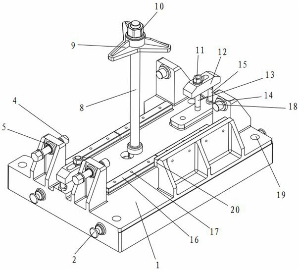
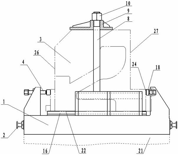
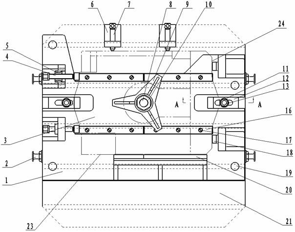
[0031] Such as figure 1 As shown in —12, a special fixture for multi-face milling and boring of large parts, including fixture body 1, lifting bolt 2, compression screw 4, movable handle compression screw 7, star-shaped pressure plate 9, positioning plate A16, positioning pillar 18 and The positioning plate B20, the fixture body 1 is a cast-molded workpiece, the fixture body 1 at the bottom is a skeleton-type cuboid base, and the three side edges on the left side, the front side and the right side of the top are fixedly connected with raised support bodies, Bushings 5 ​​are installed in the two supporting bodies spaced apart on the left side, and a horizontal compression screw 4 is threaded in the bushings 5, and the two supporting bodies spaced apart on the right side are fixedly connected respectively. There is a positioning pillar 18 in the horizontal direction, and the positioning surface of the positioning pillar 18 faces to the left; on the rear side of the fixture body ...


PUM


Abstract

The invention discloses a special clamp for multi-surface milling and boring of large parts, and belongs to the technical field of machining of artillery parts. The clamp comprises a clamp body, lifting bolts, a compression screw, a movable handle compression screw, a star-shaped pressing plate, positioning plates A, a positioning supporting column and a positioning plate B; supporting bodies are fixedly connected to the left side, the front side and the right side of the top of the clamp body, the compression screw is in threaded connection with the interior of the supporting body on the left side, and the positioning supporting column is connected in the supporting body on the right side; a movable jackscrew seat is arranged in a machine tool groove of a machine tool workbench and is in threaded connection with the movable handle compression screw; a long screw in the vertical direction is fixedly connected to the center of the upper plane of the clamp body in a threaded mode, and the positioning plates A are mounted on the front side and the rear side of the long screw and on the upper plane of the clamp body; the lifting bolts are in threaded connection to the two sides of the clamp body, and the positioning plate B is connected to the back of the supporting body on the front side of the upper plane of the clamp body. Grooves and holes in the three surfaces of a workpiece can be machined through one-time clamping.

Description

technical field [0001] The invention relates to a special fixture for multi-face milling and boring of large parts, which belongs to the technical field of machining of artillery parts. Background technique [0002] The breech of a certain artillery product is a large part with complex structure, which is difficult to process. Its shape is a cube with a through hole in the middle. It is necessary to process grooves and holes with complex structures on all sides of the part. The processing plan of this part in the scientific research stage is to align and clamp on ordinary milling machines and ordinary boring machines, and process the grooves and holes on each surface separately. After the successful trial production, the product is now transferred to mass production, and the processing procedures are more complicated and cumbersome. The production efficiency is not high, which affects the production schedule and economic benefits; in order to improve production efficiency, t...

Claims


Application Information

Patent Timeline
Patent Type & Authority Applications(China)
IPC IPC(8): B23Q3/06
CPCB23Q3/06B23Q3/062
Inventor 李娟黑玉龙李大光罗宏松王耀武付丽秋刘德胜刘炳鑫冯彩霞杨峰陈建新关鹏付航方斌黄英邢晓旭郜聆羽江坤殷嘉源黄颖金勇方玉云王友义李玉凤赵翔宇冷立书宁瑞明胡宏亮韩微商咏梅王春艳王洪亮田玉齐樊兆升张友吉洪恒武孟庆国李鹤
Owner QIQIHAR NORTH MACHINERY CORP
Why Eureka
Try Eureka