Lubricating oil valve controlled by bypass air

A technology of lubricating oil and valves, which is applied in the direction of engine lubrication, lubricating oil control valves, lubricating parts, etc., can solve problems such as unsatisfactory, unmatched control of one-way valves, etc., achieve high reliability, reduce structural weight, and expand The effect of controllable range

Active Publication Date: 2021-09-24
AECC SHENYANG ENGINE RES INST
View PDF7 Cites 0 Cited by
  • Summary
  • Abstract
  • Description
  • Claims
  • Application Information

AI Technical Summary

Problems solved by technology

[0005] 1) The one-way valve with throttle cannot be matched with the aerodynamic state of the high-altitude engine. In order to ensure the reliability of the mechanical system, it is only used to reduce the oil supply when the engine is starting, and it cannot meet the requirements of engine starting to ground idle, high-altitude air idle, Design requirements for most working conditions such as throttling at high altitude and in the air;

Method used


Image

  • Lubricating oil valve controlled by bypass air
  • Lubricating oil valve controlled by bypass air
  • Lubricating oil valve controlled by bypass air

Examples


Embodiment Construction

[0066] In order to make the purpose, technical solution and advantages of the application more clear, the technical solution in the embodiment of the application will be described in more detail below in conjunction with the drawings in the embodiment of the application.

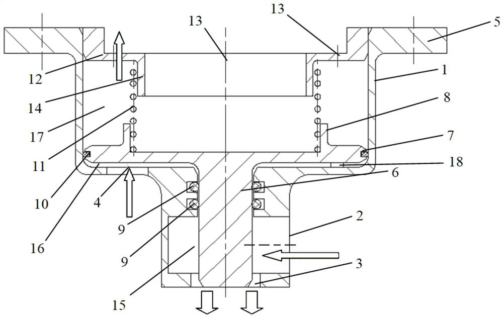
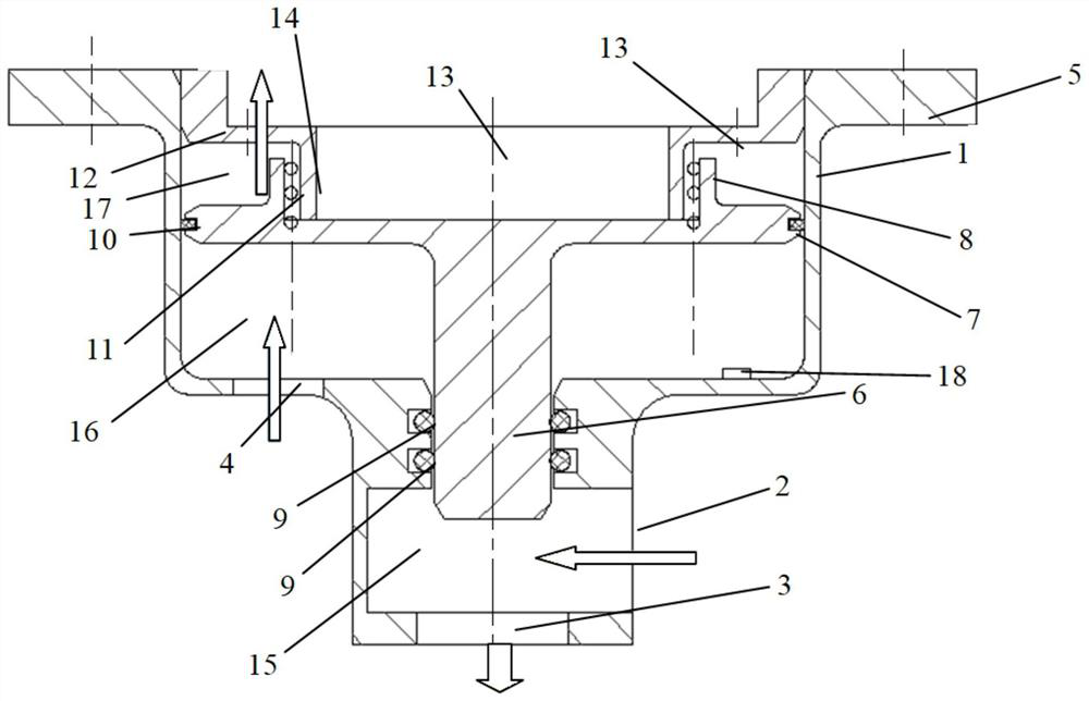
[0067]like figure 1 The throttling state of the lubricating valve controlled by external air and figure 2 As shown in the non-throttling state of the lubricating oil valve controlled by external air, the oil valve controlled by external air provided by this application mainly includes: valve housing 1, T-shaped valve core 6, plug cover 12, spring 11, etc. .

[0068] The valve housing 1 has an accommodating cavity, on the side of the valve housing 1 there is an oil inlet 2 perpendicular to the axis of the valve housing, on the lower end of the valve housing 1 there is an oil outlet 3 arranged along the axis of the valve housing, The lubricating oil outlet 3 communicates with the lubricating oil inlet 2, an...


PUM


Abstract

The invention provides a lubricating oil valve controlled by bypass air. The lubricating oil valve comprises a valve shell with a containing cavity, a T-shaped valve element, a blanking cap and a spring, wherein a lubricating oil inlet is formed in the side edge of the valve shell, a lubricating oil outlet is formed in the lower end of the valve shell, and the lubricating oil outlet communicates with the lubricating oil inlet; a step part is arranged in the middle of the valve shell; a bypass air inlet communicating with the containing cavity is formed in the step part; the T-shaped valve element is arranged in the containing cavity and can adjust the lubricating oil circulation amount between the lubricating oil inlet and the lubricating oil outlet; a sealing groove is formed in the outer side of the T-shaped valve element; a piston ring is arranged in the sealing groove; an outer guide sleeve of the spring is arranged on the T-shaped valve element; a sealing ring is arranged between the end of the T-shaped valve element and the valve shell; the blanking cap is fixedly connected with the valve shell,;a through hole communicating with the atmospheric environment is formed in the blanking cap; an inner guide of the spring is arranged on the blanking cap; and the spring is arranged between the T-shaped valve element and the blanking cap. By building a steady-state control model of the lubricating oil valve in a low state and a steady-state control model of the lubricating oil valve in a high state, opening and closing of the lubricating oil valve under bypass air control are achieved.

Description

technical field [0001] The application belongs to the technical field of aero-engines, in particular to an oil valve controlled by external air. Background technique [0002] The main bearing cavity of the advanced aero-engine is sealed by the full-envelope outer culvert gas seal method, and the lubricating oil supply system adopts a constant pressure differential oil supply scheme in the state above the idle state. Near the left boundary of the flight envelope, the aero-engine is in the idle state. Or throttling state, the sealing pressure difference of the main bearing cavity is very small, so that there is a risk of lubricating oil leakage at the sealing part of the bearing cavity, which will lead to an increase in the consumption of the lubricating oil system and affect the endurance, and the lubricating oil will leak into the main channel of the engine And cause the lubricating oil to coke or even catch fire and other failures. [0003] At present, advanced aero-engine...

Claims


Application Information

Patent Timeline
Patent Type & Authority Applications(China)
IPC IPC(8): F16N25/00F16N23/00
CPCF16N25/00F16N23/00
Inventor 郁丽左斌辉李国权
Owner AECC SHENYANG ENGINE RES INST
Why Eureka
Try Eureka