Sub-connector and wafer thereof

A technology of connectors and chips, which is applied in the direction of connection, two-part connection device, and parts of the connection device, can solve the problems of inability to form differential pair circumferential shielding and differential pair shielding, and achieve structural strength assurance and convenience Effect of processing and enhancing the shielding effect

Active Publication Date: 2021-09-24
CHINA AVIATION OPTICAL-ELECTRICAL TECH CO LTD
View PDF8 Cites 1 Cited by
  • Summary
  • Abstract
  • Description
  • Claims
  • Application Information

AI Technical Summary

Problems solved by technology

[0003] Since the prior art only bends the crimped fisheye on one side of the shielding plate, and the body of the bent fisheye structure is only attached to the side of the wafer insulator in a planar manner, it is impossible to form a pair of differential The shielding of the pair in the three-dimensional space, and since there is no shielding plate on the other side of the wafer, it is impossible to form a circumferential shielding of the differential pair in the three-dimensional space

Method used


Image

  • Sub-connector and wafer thereof
  • Sub-connector and wafer thereof
  • Sub-connector and wafer thereof

Examples


Embodiment Construction

[0063] The technical solutions of the present invention will be described in detail below in conjunction with the accompanying drawings and preferred embodiments.

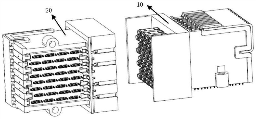
[0064] see figure 1 , a high-speed orthogonal connector of the present invention, including two matching sub-connectors, defining the contact end of the signal terminal as the shape of the receiving cavity, or a sub-connector whose contact end plays the role of the receiving cavity is a curved female The connector 10 defines that the contact end of the signal terminal is in a contained form and forms a needle-like form. Another sub-connector is a bent male connector 20, where "bent" means that the two ends of the connector have a 90° bend fold.

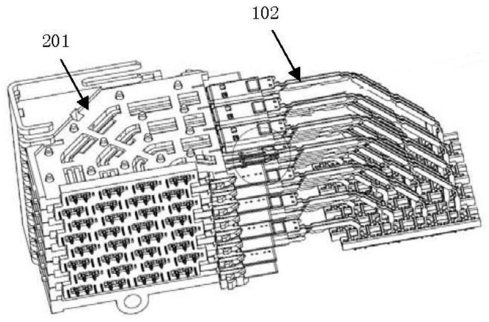
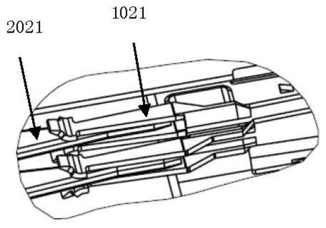
[0065] see figure 2 , the bent female connector includes a plurality of bent mother wafers 101 distributed in parallel, and the bent female signal terminal 102 on the same bent mother wafer has a contact end, a crimping end and a terminal body connecting the contact en...


PUM


Abstract

The invention discloses a sub-connector which comprises a plurality of wafers installed in parallel, each wafer comprises an insulator and shielding plates installed on the two sides of the insulator, differential pairs are arranged in the insulators, the shielding plates on the two sides are bent at the crimping ends of the differential pairs to form a plurality of shielding cavities, and each shielding cavity accommodates the crimping end of one differential pair. The two sides of the wafer are both provided with the shielding plates, and the shielding plate on each side is bent in the direction orthogonal to the shielding plate to form the folded sheet so as to form the side wall orthogonal to the shielding plate, so that the three-dimensional and circumferential differential pair isolation cavity is formed in the contact area of the differential pair and the circuit board. In the view from the crimping end, the differential pairs are fully surrounded by the shielding plate and the folding sheet, and at the same time, a GGSSGGSSGG arrangement form is still formed at the crimping end, so that the shielding effect is ensured.

Description

technical field [0001] The invention relates to a high-speed sub-connector and its chip. Background technique [0002] In the prior art, a high-speed sub-connector includes several wafers mounted side by side. Each wafer includes an insulator and a shielding plate disposed on one side of the insulator. Differential pairs for transmitting high-speed signals are installed in the insulator. In the prior art, the shielding plate is only provided on one side of the wafer, and the fisheye crimping end of the shielding plate is bent inwards on the basis of the narrow side coupling of the wafer, so that the fisheye crimping end of the shielding plate is The end and the crimp end of the differential pair are on the same straight line, thereby realizing the classic general coplanar waveguide model of GSSG. [0003] Since the prior art only bends the crimped fisheye on one side of the shielding plate, and the body of the bent fisheye structure is only attached to the side of the wafer...

Claims


Application Information

Patent Timeline
Patent Type & Authority Applications(China)
IPC IPC(8): H01R24/00H01R13/02H01R13/40H01R13/502H01R13/648
CPCH01R24/00H01R13/02H01R13/40H01R13/502H01R13/648
Inventor 马陆飞张爽王占云侯少杰周国奇鲁中原刘成荫
Owner CHINA AVIATION OPTICAL-ELECTRICAL TECH CO LTD
Why Eureka
Try Eureka