
Multi-beam low-orbit satellite communication downlink resource dynamic allocation method

A satellite communication and dynamic allocation technology, applied in electrical components, radio transmission systems, transmission systems, etc., can solve the problem of not meeting the needs of multi-user terminal transmission services, tracking user terminals to accommodate a small number of user terminals, and unable to meet the high requirements of multi-user terminals. Efficiency and other issues, to achieve the effect of good dynamic resource allocation capability, reduction of average service delay, and improvement of resource utilization

Active Publication Date: 2021-09-28
10TH RES INST OF CETC
View PDF8 Cites 5 Cited by
  • Summary
  • Abstract
  • Description
  • Claims
  • Application Information

AI Technical Summary

Problems solved by technology

This method has a good service guarantee capability in a satellite communication system with a small number of user terminals (the number of user terminals does not exceed the number of beams K), but it has great limitations in the number of user terminals and cannot meet the requirements of multi-user terminal transmission. service requirements
[0006] Existing technical solutions have their own limitations. The fixed-pattern beam-hopping allocation method has problems such as low resource utilization and high requirements for user terminal receiving capabilities. The beam allocation method for tracking user terminals has the problem of accommodating a small number of user terminals.
Therefore, the existing technical solutions cannot meet the allocation requirements of high efficiency under multi-user terminals and taking into account the receiving capacity of user terminals

Method used


Image

  • Multi-beam low-orbit satellite communication downlink resource dynamic allocation method
  • Multi-beam low-orbit satellite communication downlink resource dynamic allocation method
  • Multi-beam low-orbit satellite communication downlink resource dynamic allocation method

Examples


Embodiment Construction

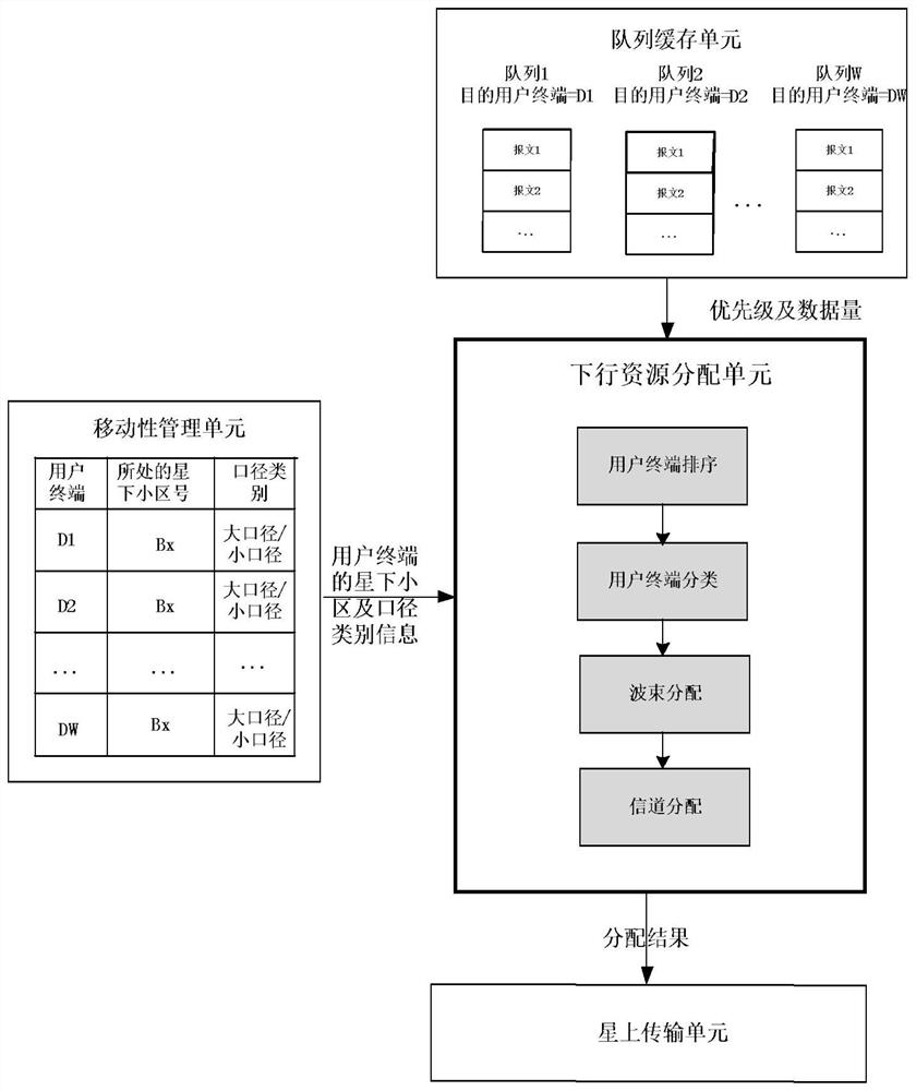
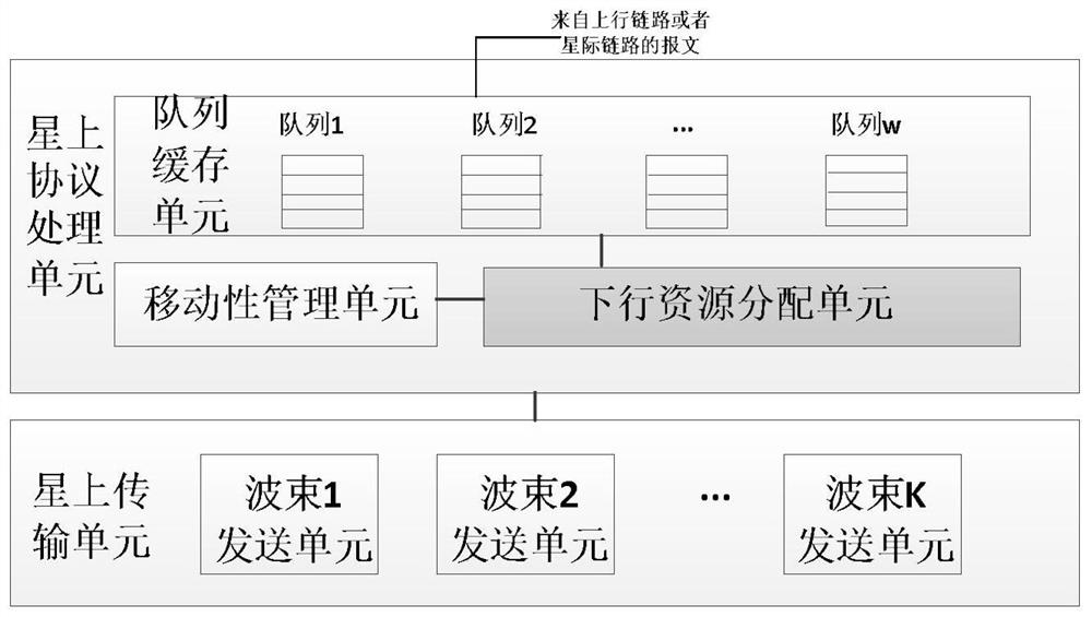
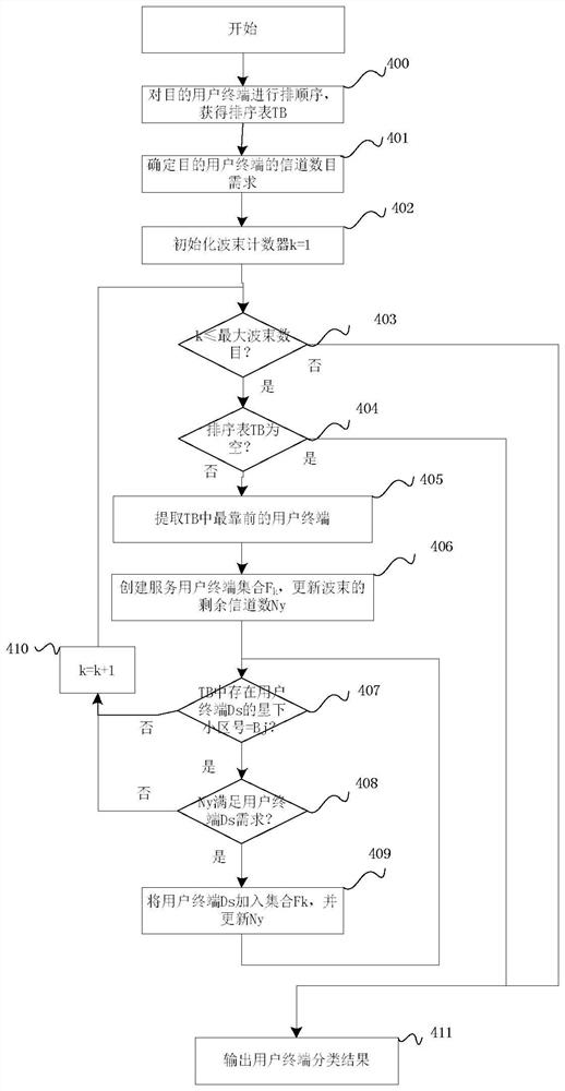
[0021] see figure 1 . According to the present invention, the downlink resource allocation unit of the multi-beam low-orbit satellite communication system divides the total bandwidth of each beam into several mutually orthogonal channels in the frequency domain, allocates one channel for small-diameter user terminals, and allocates one channel for large-diameter user terminals. Multiple continuous channels; the satellite's queue buffer unit receives and buffers the messages to be sent from the uplink or the interstellar link, and establishes buffer queues for messages of different purpose user terminals, and the data volume and priority of each buffer queue level to the downlink resource allocation unit; the downlink resource allocation unit obtains real-time user terminal sub-satellite cell information from the mobility management unit, as well as the priority and data volume provided by the queue buffer unit, according to the priority and data volume of each buffer queue. ...


PUM


Abstract

The invention discloses a multi-beam low-orbit satellite communication downlink resource dynamic allocation method, and the method has higher resource utilization rate and higher allocation reliability. The method is realized through the following technical scheme: the method comprises the steps: in a multi-beam low-orbit satellite communication system, enabling a downlink resource allocation unit to divide the total bandwidth of each beam into a plurality of mutually orthogonal channels; acquiring a sub-satellite cell number and aperture category information of each user terminal in real time; enabling a queue cache unit of a satellite to receive and cache to-be-sent messages from an uplink or an interstellar link, respectively establishing cache queues for messages of different target user terminals, and sending data volumes and priorities of the cache queues to a downlink resource allocation unit to classify the target user terminals; establishing a coupling information matrix by combining the beam distribution result information of the previous distribution period; and at the allocation moment of each allocation period, dynamically allocating satellite beams and channel resources as required, and sending resource allocation result information to an on-satellite transmission unit.

Description

technical field [0001] The invention relates to a method for dynamically allocating downlink resources applicable to a multi-beam low-orbit (LEO, Low Earth Orbit) satellite communication system. Background technique [0002] Due to its ability to achieve seamless global coverage, the low-orbit constellation satellite communication system has outstanding advantages such as small transmission loss, short delay, strong invulnerability and anti-interference, and small and portable terminals compared with medium and high-orbit satellite communication systems. In the civilian field, the low-orbit constellation satellite communication system effectively makes up for the lack of coverage of low-density business environments (such as remote areas, coastal islands, and deserts) due to the limitations of geographical conditions and economic factors on the ground network, and can truly realize Seamless coverage on a global scale; in areas where major natural disasters occur, most of the...

Claims


Application Information

Patent Timeline
IPC IPC(8): H04B7/185
CPCH04B7/18513Y02D30/70
Inventor 王昭黄盛夏晓巍
Owner 10TH RES INST OF CETC
Learn More