

Medical needle knife with auxiliary needle applying device
An acupuncture and acupuncture handle technology, which is applied in acupuncture, medical science, medicine and other fields, can solve the problems of inconvenient switching, delaying treatment time, affecting the therapeutic effect, etc., and achieve flexible and convenient use and switching, and save treatment. time, and the effect of improving the efficiency of diagnosis and treatment
- Summary
- Abstract
- Description
- Claims
- Application Information
AI Technical Summary
Problems solved by technology
Method used
Image

Examples
Embodiment 1
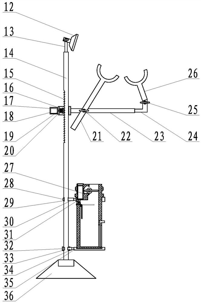
[0043] Such as figure 1 , 2 As shown in and 3, it also includes an auxiliary needle application device, the auxiliary needle application device includes an auxiliary bracket, the auxiliary bracket includes a base, a pole and a cross bar, the pole is vertically installed on the base, and passes through the top of the pole The sliding positioning device is equipped with a cross bar, and a left arm support and a right arm support are installed on the cross bar; a medical waste collection device is arranged at the bottom of the vertical bar.
[0044] The sliding positioning device includes a sliding ratchet rack longitudinally installed on the side wall of the vertical rod, and the tip of the sliding ratchet rack is arranged upward; a sliding sleeve is arranged at the installation end of the cross bar, and A ratchet block is arranged inside the barrel, and more than two ratchets are arranged on the side of the ratchet block facing the sliding ratchet bar, and the ratchets can mes...
Embodiment 2
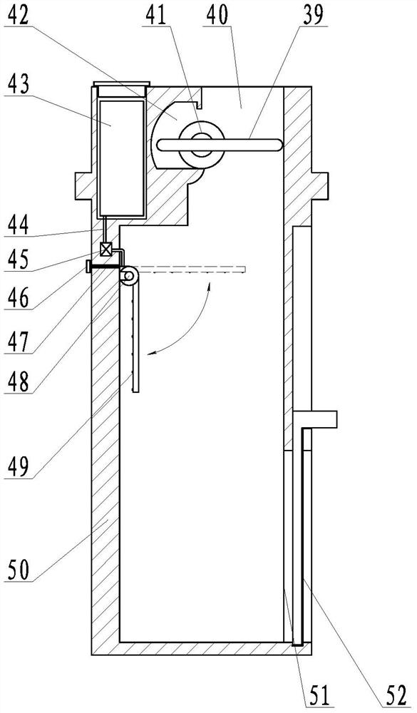
[0056] Such as Figure 4-6 As shown, the number of the needle-knife body is two groups, respectively the first needle-knife group and the second needle-knife group, and needle-knife heads of different specifications are respectively installed on the first needle-knife group and the second needle-knife group; The upper end of the first needle-knife group is fixed on the needle-knife handle, and the second needle-knife group storage slot is opened in the middle section of the first group of needle-knife group. The needle-knife switch includes a left shaft insertion hole and a right rotation shaft insertion hole. and the rotating shaft of the needle-knife body, the left and right rotating shaft jacks are respectively provided on the left and right sides of the upper end of the second needle-knife group storage slot, the upper end of the second needle-knife group is provided with the rotating shaft of the needle-knife body, and the rotating shaft of the needle-knife body The left ...
Embodiment 3
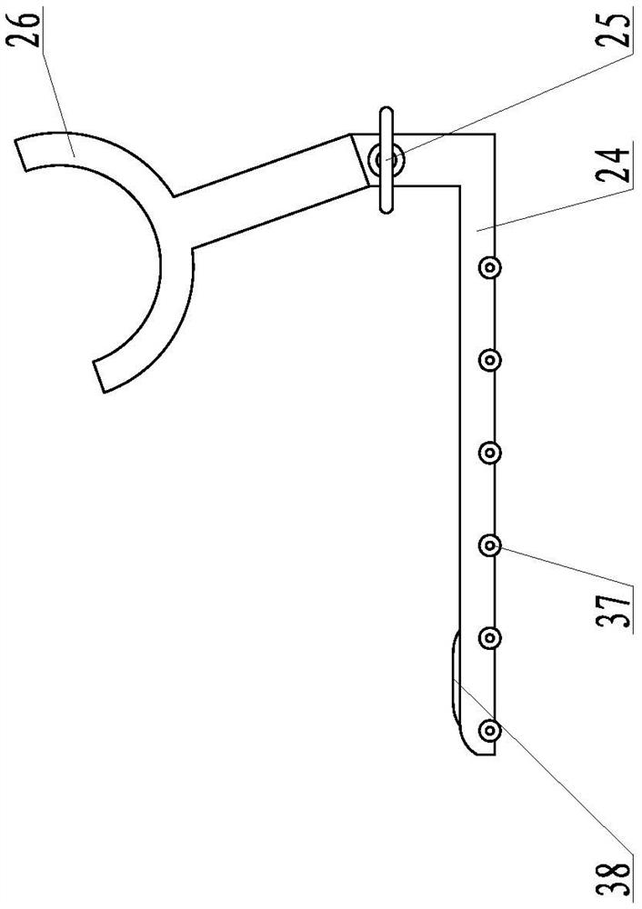
[0061] Such as Figure 7-9 As shown, the auxiliary needle applicator also includes a sterilized hemostatic device, the sterilized hemostatic device includes a hemostatic main rod, a fixed ring is arranged at the upper end of the hemostatic main rod, and the upper end of the hemostatic swing rod is hinged at the lower end of the hemostatic main rod; The lower end of the hemostatic pendulum is connected with a disinfection and hemostasis functional body, which includes a "∏" shaped roller bracket, which is connected and fixed to the lower end of the hemostatic pendulum in the middle of the roller bracket, and the two ends of the roller bracket are respectively provided with left and right rotation shafts. The rotating shaft is provided with a roller body between the left rotating shaft and the right rotating shaft.
[0062] The roller body includes a left roller plate and a right roller plate, the left roller plate and the right roller plate are connected through a central shaft...
PUM
 Abstract
Description
Claims
Application Information