Digestive tract foreign matter taking-out device
A technology for removing the device and the digestive tract, which is applied in the field of auxiliary medical treatment, can solve the problems of long operation time, secondary damage, and does not have the function of extending into the tube, and achieves the effect of improving stability and preventing reverse deflection.
- Summary
- Abstract
- Description
- Claims
- Application Information
AI Technical Summary
Problems solved by technology
Method used
Image

Examples
Embodiment 1
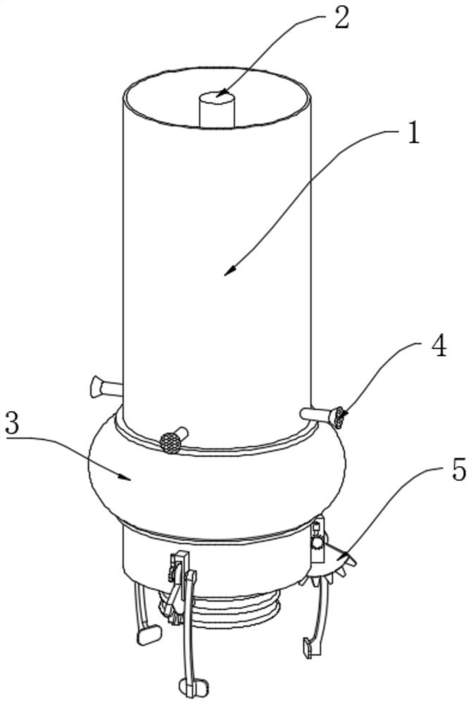
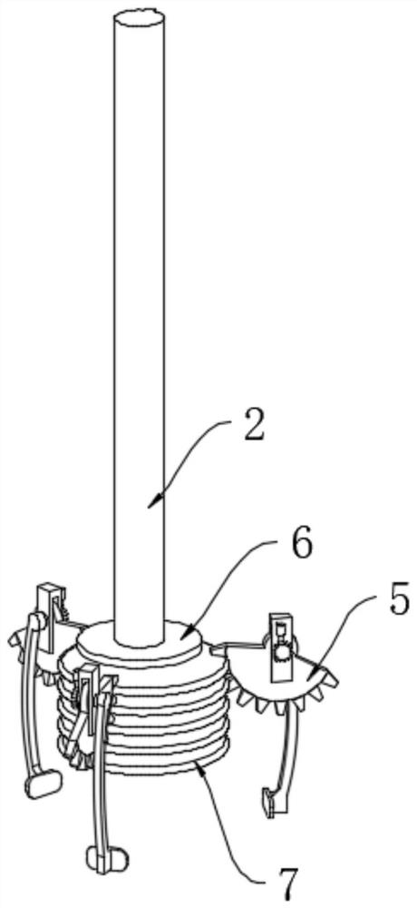
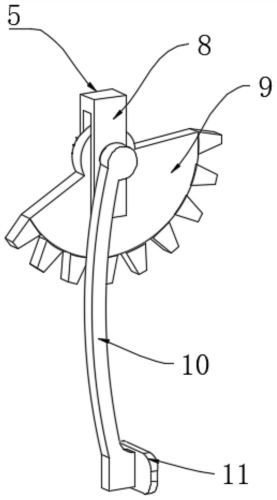
[0032] see Figure 2-3, a device for taking out foreign matter in the digestive tract, comprising an insertion tube 1, a spline shaft 2 is provided in the inner cavity of the insertion tube 1, a mounting plate 6 is fixedly connected to the bottom of the spline shaft 2, and a mounting plate 6 is fixedly connected to the bottom of the mounting plate 6 The ring tooth rack 7 is movably connected with the clamping mechanism 5 on the outer wall of the insertion tube 1 relative to the position of the ring tooth rack 7. The clamping mechanism 5 is provided with three groups, and is evenly distributed on the bottom of the insertion tube 1. The clamping mechanism 5 includes a mounting frame 8, the mounting frame 8 is fixedly connected with the outer wall of the pipe 1, the inner cavity of the mounting frame 8 is movably connected with a toothless gear 9, the toothless gear 9 is meshed with the ring rack 7, and the mounting frame 8 The outer wall is movably connected with a clamp arm 10 ...
Embodiment 2
[0035] see image 3 , is basically the same as the first embodiment, furthermore, the splint 11 is an elastic structure, and the inner wall of the splint 11 is provided with anti-skid lines.
[0036] Improve the stability of clamping by setting anti-skid lines.
[0037] see Figure 4 The side of the mounting frame 8 far away from the clamp arm 10 is provided with an anti-reverse mechanism, the anti-reverse mechanism includes a ratchet 15, and the ratchet 15 is coaxially fixed with the axial center of the tooth-missing gear 9, and the outer wall of the mounting frame 8 is relatively The upper position is fixedly connected with the limiting housing 12, the inner cavity of the limiting housing 12 is slidingly connected with the limiting block 13, the bottom of the limiting block 13 is engaged with the ratchet 15, and the bottom of the limiting block 13 is connected with the bottom of the limiting housing 12. A spring 14 is arranged between the inner walls.
[0038] When the too...
Embodiment 3
[0046] see Figure 7 , is basically the same as Embodiment 2, furthermore, the top of the jet housing 27 is fixedly connected with a jet tube one 32, the bottom of the jet tube one 32 communicates with the inner cavity of the jet housing 27, and the inner wall of the jet tube one 32 slides A piston block 33 is connected, a spring 2 34 is arranged between the top of the piston block 33 and the inner wall of the jet tube 1 32, and the side wall of the jet tube 1 32 near the conduit 31 is fixedly connected with an air guide tube 1 35, an air guide tube 1 35 The end away from the jet tube 1 32 extends to the inner cavity of the conduit 31 , and the outlet position is inclined.
[0047] After the protective fluid in the inner cavity of the liquid storage bag 30 is squeezed out, as the piston plate 28 continues to move to the right, there is still pressure in the inner cavity of the jet housing 27, and when the pressure in the inner cavity of the jet housing 27 is gradually greater ...
PUM
 Abstract
Description
Claims
Application Information
 - R&D
- Intellectual Property
- Life Sciences
- Materials
- Tech Scout
- Unparalleled Data Quality
- Higher Quality Content
- 60% Fewer Hallucinations
Browse by: Latest US Patents, China's latest patents, Technical Efficacy Thesaurus, Application Domain, Technology Topic, Popular Technical Reports.
© 2025 PatSnap. All rights reserved.Legal|Privacy policy|Modern Slavery Act Transparency Statement|Sitemap|About US| Contact US: help@patsnap.com