A process for dissolving copper in electrolytic copper foil with reduced energy consumption

A technology of electrolytic copper foil and copper melting, applied in the direction of feeding device, chemical/physical/physical chemical process, chemical instrument and method, etc., can solve the problems of low copper melting efficiency, untimely operation, and failure to reach production efficiency, etc. , to avoid too few copper coils, reduce production efficiency, and reduce the efficiency of copper dissolution

Active Publication Date: 2022-08-05
JIANGXI XINBORUI TECH CO LTD
View PDF17 Cites 0 Cited by
  • Summary
  • Abstract
  • Description
  • Claims
  • Application Information

AI Technical Summary

Problems solved by technology

[0003] In the existing copper melting production, the efficiency of copper melting is too low, and it is required to manually adjust the feeding speed according to the current copper melting speed, so that the space of the copper melting device can be fully utilized, but the manual operation error is large, and the operation is not timely. Moreover, the workload is heavy, the production cost is increased, and the function of improving production efficiency cannot be achieved. Therefore, we propose a material process for electrolytic copper foil melting copper that reduces energy consumption to solve the above-mentioned problems.

Method used


Image

  • A process for dissolving copper in electrolytic copper foil with reduced energy consumption
  • A process for dissolving copper in electrolytic copper foil with reduced energy consumption
  • A process for dissolving copper in electrolytic copper foil with reduced energy consumption

Examples


Embodiment 1

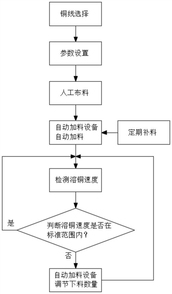
[0035] refer to Figure 1-6 , an electrolytic copper foil dissolving copper material process for reducing energy consumption, comprising the following steps:

[0036] S1. Copper wire selection: Dissolved copper is a corrosion and dissolution reaction on the surface of metal copper. The larger the surface area of ​​the metal copper participating in the reaction, the more oxygen and solution it is exposed to. The larger the surface area of ​​the metal copper, the faster the corrosion rate per unit time. , the faster the reaction generates copper ions; the purpose of changing the φ3mm copper wire used for dissolving copper to φ1.5mm copper wire is to increase the surface area of ​​metal copper, and the surface area of ​​the same weight of metal copper when feeding is equal to increase. doubled;

[0037] S2. Parameter setting: According to the volume of the copper melter 7 and the amount of ventilation, set the weight of the copper coil 5 in the copper melter 7 to prevent too few...

Embodiment 2

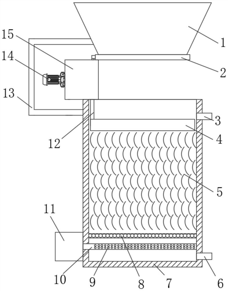
[0042] This embodiment is improved on the basis of the first embodiment: the automatic feeding device in step S4 is fixedly connected to the copper melter 7, the copper coil 5 is arranged inside the copper melter 7, and the inside of the copper melter 7 is provided with a filter The net 8, the copper coil 5 is located above the filter screen 8, one side of the copper dissolver 7 is provided with a liquid inlet pipe 3 and a liquid outlet pipe 6 that communicate with each other, and the bottom of one side of the copper dissolver 7 is fixedly connected with an air pump 11, and the air pump The air outlet of 11 is fixedly connected with a connected air outlet pipe 10, and the air outlet pipe 10 is located below the filter screen 8, and a U-shaped plate 13 is fixedly connected to the top of one side of the copper melter 7, and one end of the U-shaped plate 13 is fixedly connected with an outlet. Hopper 1, the top of the copper melter 7 is provided with a discharge assembly for disch...

Embodiment 3

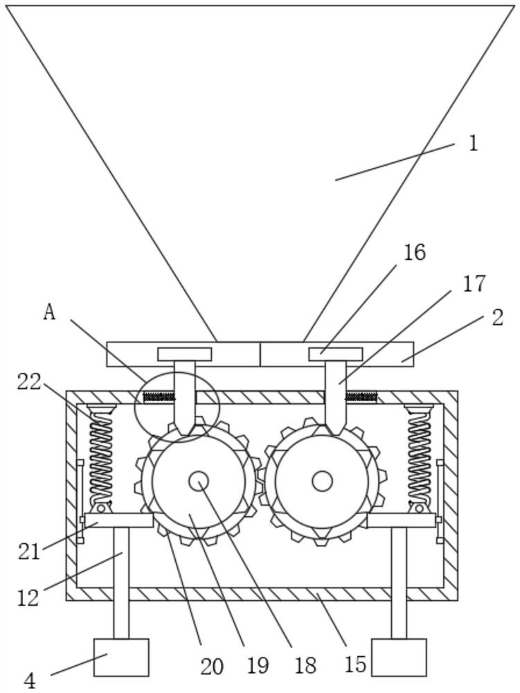
[0044] This embodiment is improved on the basis of the first embodiment: the inner walls on both sides of the fixed box 15 are slidably connected with a first sliding plate 21 that meshes with the pinion 19 , the top of the first sliding plate 21 and the top inner wall of the fixed box 15 are slidably connected The same tension spring 22 is fixedly connected between them, and the bottom of the first sliding plate 21 is fixedly connected with a lifting rod 12. The bottom of the lifting rod 12 slides through the fixed box 15 and extends to the bottom of the fixed box 15. The inner wall of the copper melter 7 Two test boxes 4 that are symmetrically arranged are slidably connected, and the two test boxes 4 are respectively located below the two lifting rods 12 . The bottom of the lifting rods 12 is fixedly connected with a second sliding plate 27 , and the second sliding plate 27 is connected to the test box 4 . The inner walls on both sides of the test box 4 are slidably connected...


PUM


Abstract

The invention belongs to the field of electrolytic copper foil production, in particular to a process for dissolving copper in electrolytic copper foil for reducing energy consumption. In the case of the existing copper dissolving production, the efficiency of dissolving copper is too low, and it is required to manually adjust the copper dissolving speed according to the current copper dissolving speed. The speed of feeding is adjusted, so that the space of the copper melter can be fully utilized, but the manual operation error is large, the operation is not timely, and the workload is large, which increases the production cost. The following scheme is now proposed, which includes the following steps: copper wire Selection: Dissolving copper is a corrosion and dissolution reaction on the surface of metal copper. The larger the surface area of ​​metal copper participating in the reaction, the more oxygen and solution it is exposed to. In the present invention, by selecting finer copper coils, the use of copper coils can be reduced The coil is placed horizontally to improve the utilization rate of air, and the amount of feed is automatically adjusted according to the current copper melting speed. While making full use of the copper melting vessel space, it can also improve the copper melting efficiency and greatly reduce the workload of workers.

Description

technical field [0001] The invention relates to the technical field of electrolytic copper foil production, in particular to a process for dissolving copper material for electrolytic copper foil that reduces energy consumption. Background technique [0002] Dissolved copper production is the first process in the production of electrolytic copper foil. It uses dilute sulfuric acid aqueous solution and oxygen to dissolve metal copper into copper sulfate aqueous solution, and electrodeposits metal copper foil in the electrolysis process. Copper foil is used to make various electronic products. Such as circuit boards, lithium-ion batteries, etc. [0003] When the existing copper melting is produced, the efficiency of melting copper is too low, and it is required to manually adjust the feeding speed according to the current copper melting speed, so that the space of the copper melting device can be fully utilized, but the manual operation error is large, and the operation is not ...

Claims


Application Information

Patent Timeline
Patent Type & Authority Patents(China)
IPC IPC(8): B01J19/24B01J4/00
CPCB01J19/24B01J19/0053B01J4/007B01J4/008B01J2204/002
Inventor 陈泽仁陈星徐琪
Owner JIANGXI XINBORUI TECH CO LTD
Why Eureka
Try Eureka