Hub bearing with spline shielding structure

A hub bearing and spline technology, applied in the field of hub bearings, can solve the problems affecting the service life of the overall structure, uneven power transmission, difficult processing and assembly, etc., and achieve the effects of improving fuel economy, not easy to slip, and easy to maintain

Active Publication Date: 2021-10-01
C&U CO LTD +1
View PDF11 Cites 2 Cited by
  • Summary
  • Abstract
  • Description
  • Claims
  • Application Information

AI Technical Summary

Problems solved by technology

The traditional hub bearing connection method usually has a long spline, which is not easy to process and difficult to assemble, and due to the difficulty of processing and assembly, it is more prone to wear during use, which affects the service life of the overall structure, and the ball cage shaft There is usually a gap between the hub bearing and the hub bearing during the operation of the vehicle, so that the vehicle drive element and the hub are not in the same axis relative to the rotation axis, which is prone to problems such as abnormal starting noise and uneven power transmission

Method used


Image

  • Hub bearing with spline shielding structure
  • Hub bearing with spline shielding structure
  • Hub bearing with spline shielding structure

Examples


Embodiment Construction

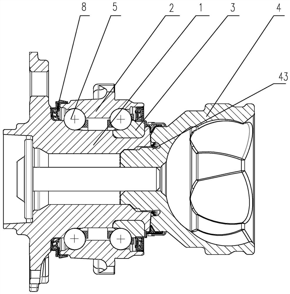
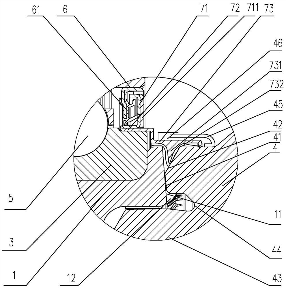
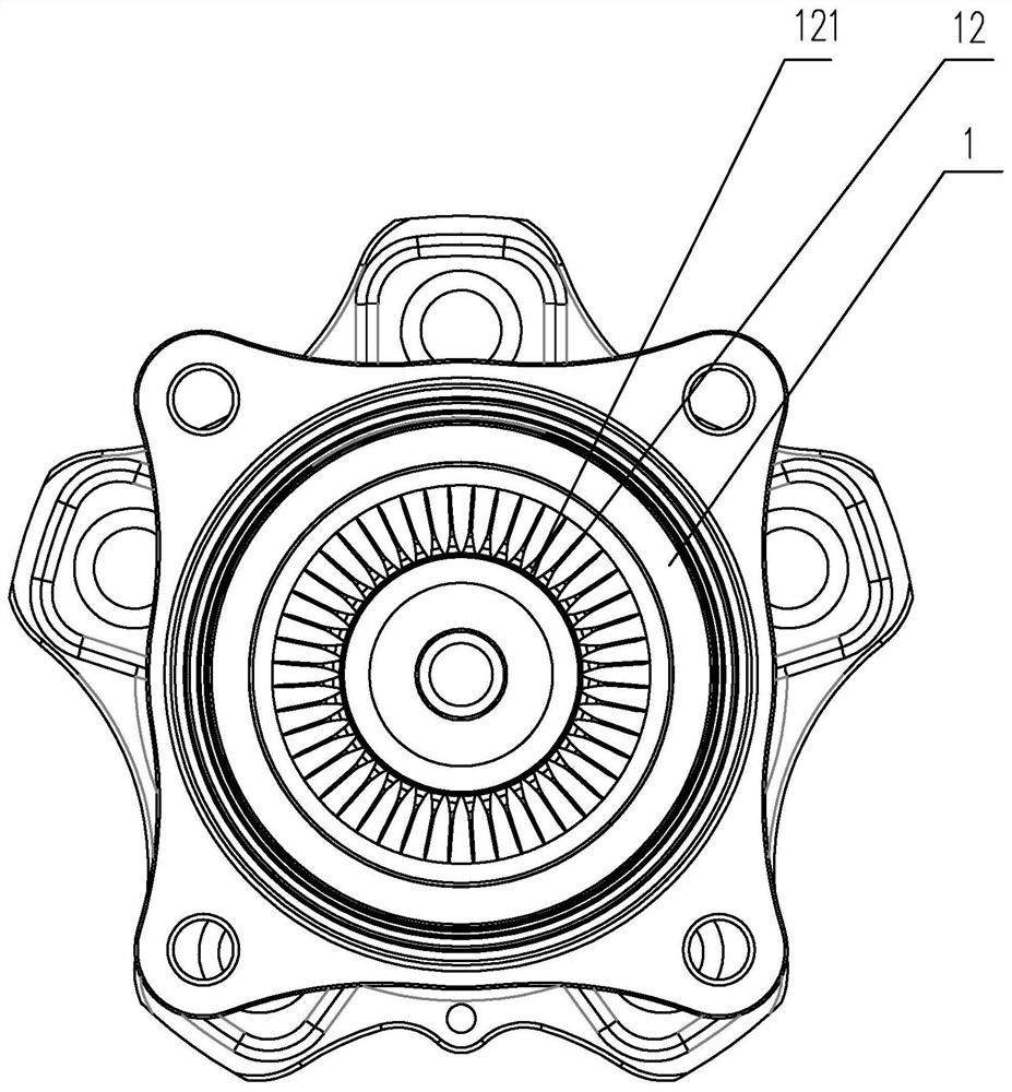
[0025] Embodiments of the hub bearing with the spline shielding structure of the present invention are as follows Figure 1 to Figure 3 As shown: including the rotary joint 4, the flange inner ring 1, the flange outer ring 2 and the connecting inner ring 3, the outer wall of the flange inner ring 1 and the flange outer ring 2 are provided with a first rolling groove, so A positioning step is also formed on the flange inner ring 1, the connecting inner ring 3 is engaged with the positioning step, and a second roll groove is formed between the outer wall of the connecting inner ring 3 and the flange outer ring 2, and the Rolling bodies 5 are arranged in the first rolling groove and the second rolling groove, and a positioning protrusion 43 is formed on the end of the rotary joint 4 facing the flange inner ring 1, and a positioning groove is arranged on the inner wall of the flange inner ring 1, The positioning protrusion 43 fits with the positioning groove in a gap, and the cont...


PUM


Abstract

The invention discloses a hub bearing with a spline shielding structure. The hub bearing comprises a rotary connector, a flange inner ring, a flange outer ring and a connecting inner ring, rolling bodies are arranged between the flange inner ring and the flange outer ring and between the connecting inner ring and the flange outer ring, and a positioning protrusion is formed at the end, facing the flange inner ring, of the rotary connector; the inner wall of the flange inner ring is provided with a positioning groove, the positioning protrusion is in clearance fit with the positioning groove, the end face of the flange inner ring is arranged to be a conical face, connecting teeth are evenly distributed on the conical face, an abutting face is formed at the end of the rotary connector, clamping teeth are arranged on the abutting face, the connecting teeth are connected with the clamping teeth in a clamped manner, and the abutting face is connected with the edge of the rotary connector through a transition inclined face; and a first sealing check ring is arranged between the flange outer ring and the connecting inner ring, the first sealing check ring extends towards the connecting teeth to form a shielding lip, the first sealing check ring comprises a shielding protrusion, and the shielding protrusion is arranged between the transition inclined face and the conical face. The hub bearing is compact in structure, the installation precision is high, power transmission is stable, and the sealing effect is good.

Description

technical field [0001] The invention relates to the technical field of hub bearings. Background technique [0002] The hub bearing of the drive wheel is usually connected with the vehicle drive element, that is, the ball cage shaft, using a pair of inner and outer splines, so as to realize the transmission of vehicle power. The traditional hub bearing connection method usually has a long spline, which is not easy to process and difficult to assemble, and due to the difficulty of processing and assembly, it is more prone to wear during use, which affects the service life of the overall structure, and the ball cage shaft There is usually a gap between the hub bearing and the hub bearing during the operation of the vehicle, which makes the vehicle drive element and the hub different from the axis of rotation, which is prone to problems such as abnormal starting noise and uneven power transmission. Contents of the invention [0003] Aiming at the deficiencies of the prior art...

Claims


Application Information

Patent Timeline
Patent Type & Authority Applications(China)
IPC IPC(8): F16C35/06F16C33/58F16C33/60F16C33/76F16C33/78F16J15/02B60B27/00
CPCF16C35/06F16C33/581F16C33/60F16C33/768F16C33/7806F16C33/7823F16C33/7816F16J15/025B60B27/0078B60B27/0005B60B27/0073F16C2226/78F16C2326/02
Inventor 胡晟胡世雄
Owner C&U CO LTD
Why Eureka
Try Eureka