A Dynamic Correction Method of Trigger Point Offset in Data Acquisition System

A data acquisition system and dynamic correction technology, which is applied in digital variable display, digital variable/waveform display, instruments, etc., can solve the problem of losing analog triggers, and achieve the effect of less operation steps, low cost, and simple derivation process

Active Publication Date: 2022-04-19
UNIV OF ELECTRONICS SCI & TECH OF CHINA
View PDF13 Cites 0 Cited by
  • Summary
  • Abstract
  • Description
  • Claims
  • Application Information

AI Technical Summary

Problems solved by technology

Although this method can solve the problem of trigger point offset, it loses the biggest feature of analog trigger, that is, it can trigger in the signal range other than the ADC code value.

Method used


Image

  • A Dynamic Correction Method of Trigger Point Offset in Data Acquisition System
  • A Dynamic Correction Method of Trigger Point Offset in Data Acquisition System
  • A Dynamic Correction Method of Trigger Point Offset in Data Acquisition System

Examples


Embodiment

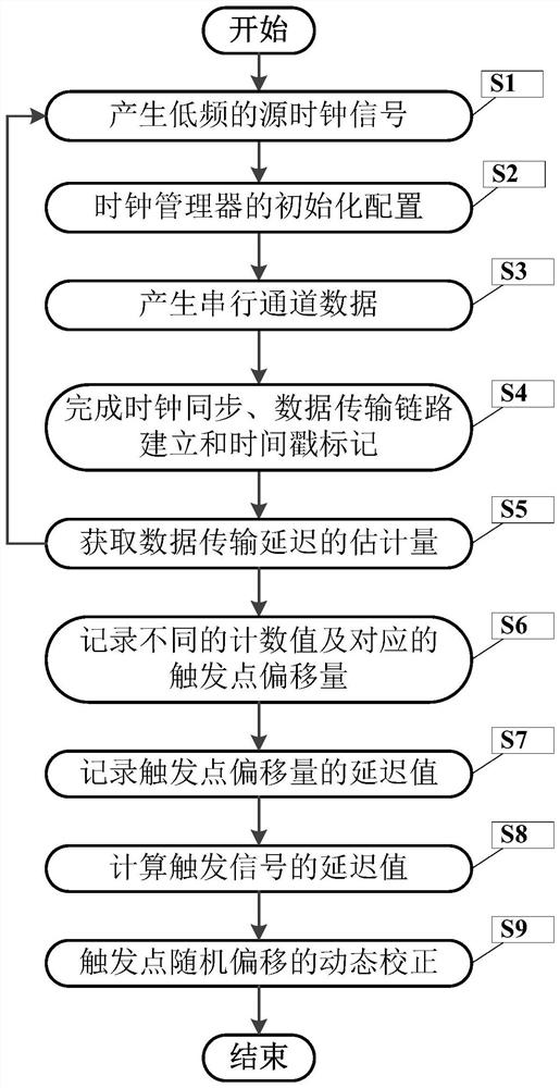
[0043] figure 2 It is a flow chart of the dynamic correction method of the trigger point offset of the data acquisition system of the present invention.

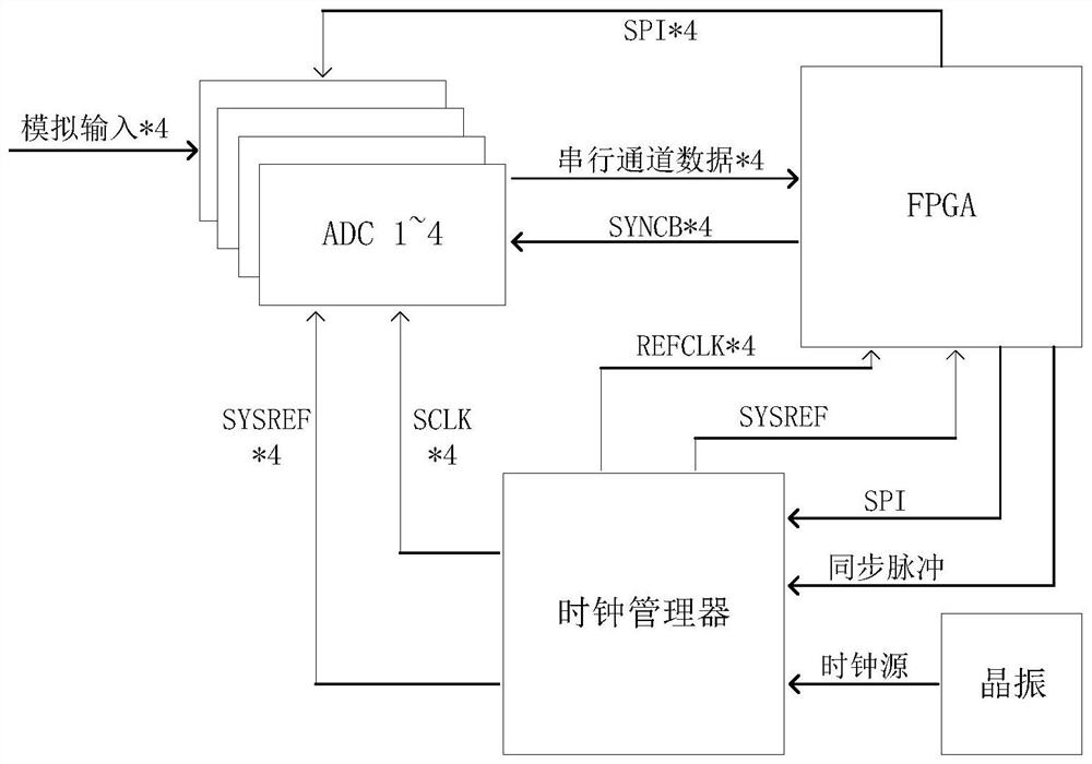
[0044] In this embodiment, in this embodiment, as figure 2As shown, we use 4 pieces of ADC (JESD204B interface) with 2.5GSPS sampling rate and 12bits resolution to sample 4 channels of analog signals and then transfer the sampled data to FPGA, such as image 3 As shown, a method for dynamic correction of trigger point offset of a data acquisition system of the present invention includes the following steps:

[0045] S1, such as Figure 4 As shown, the crystal oscillator is used to generate a low-frequency source clock signal and send it to the clock manager of the dual phase-locked loop;

[0046] S2. FPGA performs register initialization configuration on the clock manager through the SPI communication protocol; after the initialization configuration is completed, the clock manager locks and amplifies the low-frequency s...


PUM


Abstract

The invention discloses a method for dynamically correcting the offset of a trigger point in a data acquisition system. By designing a counter in the FPGA, the counter is turned on while time stamping the sampled data. When the FPGA receives the sampling point carrying the time stamp data, the counter stops counting to obtain the count value, and reads the offset of the trigger point under the current count value from the screen, and then adjusts the delay value of the trigger control signal to make the actual trigger point return to the position of the ideal trigger point, repeat The operation obtains two sets of different data, and uses the two sets of data to derive the calculation formula of the delay value of the trigger signal and the count reading value. After that, each time the power is turned on, the value of the counter is read and brought into the formula to calculate the value of the power-on. The delay value of the trigger control signal is written into the FPGA delay control unit to complete the dynamic correction of the random offset of the trigger point.

Description

technical field [0001] The invention belongs to the technical field of oscilloscopes, and more particularly, relates to a dynamic correction method for trigger point offset of a data acquisition system. Background technique [0002] In an oscilloscope system, triggering is a process of selectively selecting sampled data with a large amount of data. Take rising edge triggering as an example: the user first sets a comparison level value, and the input analog signal is compared with the comparison level in a comparator. If the input signal is greater than the comparison level value, the comparator outputs a high level, otherwise it outputs a low level, and the output result is called a comparison pulse, such as figure 1 As shown, the rising edge of the comparison pulse is the trigger edge for judging the arrival of the trigger signal. The way this type of comparison occurs before the ADC performs the analog-to-digital conversion is called analog triggering. [0003] Since the...

Claims


Application Information

Patent Timeline
Patent Type & Authority Patents(China)
IPC IPC(8): G01R13/02
CPCG01R13/0254
Inventor 黄武煌袁春友许刚张沁川杨扩军邱渡裕古军叶芃王厚军
Owner UNIV OF ELECTRONICS SCI & TECH OF CHINA
Why Eureka
Try Eureka