
Patsnap Eureka
For R&D, Patsnap Eureka makes reading and utilizing patents & technical documents easy.
Patsnap Eureka AIR
Designed for self-driven R&D workflows. Generate viable solutions, solve complex R&D challenges, empower your innovation with AI.

Patsnap Eureka Materials
Designed for material experts only. Revolutionize your material R&D, from search, analyze, to developing new materials.

TechResearch
Generate reliable direction feasibility study reports for your R&D in just a few steps.

TechSeek
Discover and master advanced knowledge NOW. Basics, ideas, possibilities, all at once.

TechMind
As an expert in R&D Theories, TechMind can generates customized viable solutions instantly.

TechRisk
Analyze your overall solution with one click, know your potential R&D risks in advance.

TechMonitor
Get weekly tech updates, stay abreast of the latest tech innovations and key insights.
Operation knob device
A technology for operating knobs and knobs, which is applied in the direction of mechanical control devices, transportation and packaging, devices for preventing/limiting/recovering the movement of parts of the control mechanism, etc., to achieve the effect of improving transmission
- Summary
- Abstract
- Description
- Claims
- Application Information
AI Technical Summary
Problems solved by technology
Method used
Image

Examples
no. 1 approach
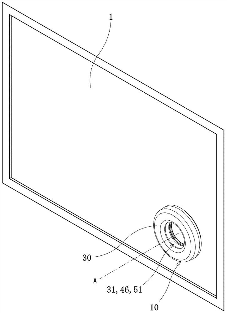
[0038] figure 1 as well as Figure 2A The operation knob device 10 according to the first embodiment of the present invention is shown. The display panel 1 provided with the operation knob device 10 has a touch detection function for detecting a user's operation through a change in electrostatic capacitance, and is mounted on an in-vehicle product such as a navigation device or a center display.
[0039] Such as figure 1 As shown, the operation knob device 10 is disposed in a predetermined operation area of the display panel 1 and protrudes from the display panel 1 toward the vehicle interior. The operating knob device 10 has a ring shape as a whole, and is arranged such that the axis A extends in a direction perpendicular to the display panel 1 . The operation knob device 10 includes one knob (operation unit) 30 , and transmits a pressing operation and a rotation operation of the knob 30 to the display panel 1 .
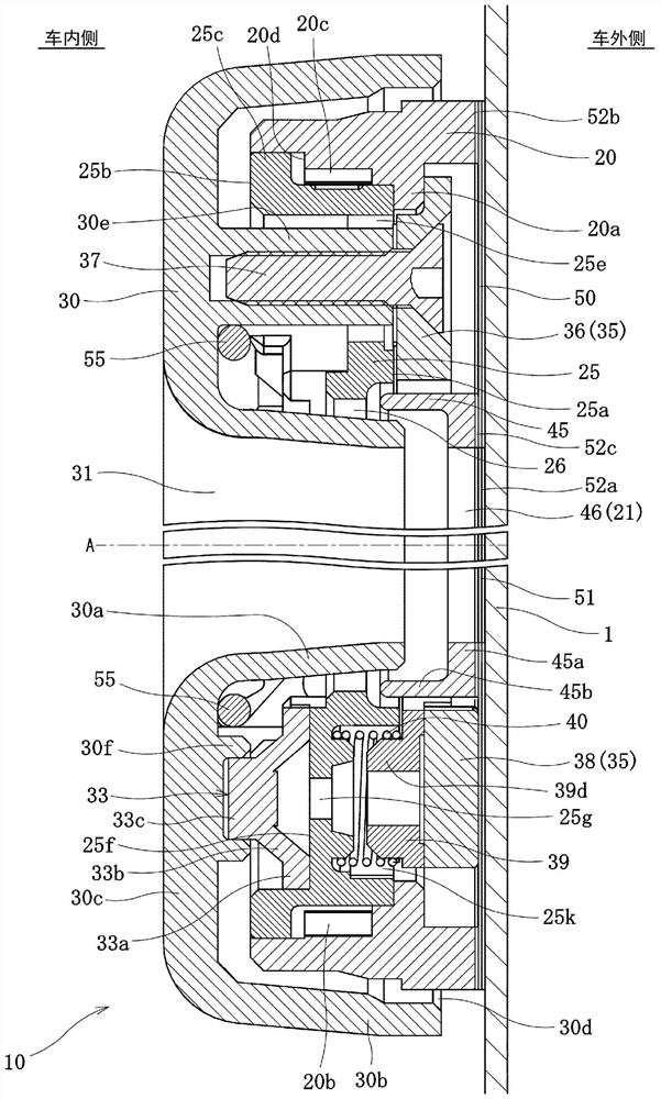
[0040] Such as Figure 2A as well as image 3 As shown...
no. 2 approach
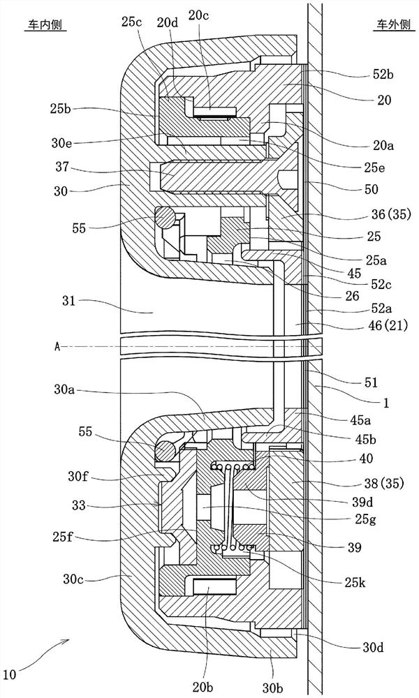
[0102] Figure 10 The operation knob device 10 of the second embodiment is shown. In this second embodiment, instead of Figure 2A The ring member 45 of the illustrated first embodiment differs from the first embodiment in that the film 50 is provided with a wall portion 50 a.
[0103] Such as Figure 11 As shown, the wall part 50a has a cylindrical shape and is provided on the inner periphery of the annular film 50 by deep drawing. refer to Figure 10 The diameter of the wall portion 50 a is set so that the wall portion 50 a protrudes between the hole wall (inner peripheral surface) of the opening portion 26 of the rotary body 25 and the inner wall portion 30 a of the knob 30 . In addition, the protrusion amount of the wall portion 50 a from the main body of the film 50 is a length between the inner peripheral surface of the rotor 25 and the inner wall portion 30 a of the knob 30 . In the inner peripheral part of the film 50 is not provided Figure 4 The adhesive layer ...
no. 3 approach
[0106] Figure 12 The operation knob device 10 of the third embodiment is shown. This third embodiment differs from the first embodiment in that a wall portion 50 b is provided on the outer periphery of the film 50 .
[0107] Such as Figure 13 As shown, the wall portion 50b has a cylindrical shape and is provided on the outer periphery of the film 50 by deep drawing. exist Figure 13 In the example shown above, the adhesive layer 52b for the holder 20 is provided on the outer peripheral portion of the film 50, but this adhesive layer 52b may not be provided. refer to Figure 12 The wall portion 50b protrudes so as to be located outside the holder 20, and is fixed to the outer peripheral surface of the holder 20 by welding.
[0108] In the operation knob device 10 of the third embodiment, the same operations and effects as those of the first embodiment can be obtained. Moreover, since the cylindrical wall part 50b is integrally provided with the film 50, the intrusion of...
PUM
 Abstract
Description
Claims
Application Information
 - R&D Engineer
- R&D Manager
- IP Professional
- Industry Leading Data Capabilities
- Powerful AI technology
- Patent DNA Extraction
Browse by: Latest US Patents, China's latest patents, Technical Efficacy Thesaurus, Application Domain, Technology Topic, Popular Technical Reports.
© 2024 PatSnap. All rights reserved.Legal|Privacy policy|Modern Slavery Act Transparency Statement|Sitemap|About US| Contact US: help@patsnap.com