A tubular solid oxide fuel cell structure

A solid oxide, fuel cell technology, used in fuel cells, fuel cell additives, fuel cell heat exchange, etc., can solve the problems of low power generation efficiency and reduced power generation at the entrance, and achieve improved overheating effect. The effect of power generation and strength improvement

Active Publication Date: 2021-11-12
CEMT CO LTD
View PDF4 Cites 0 Cited by
  • Summary
  • Abstract
  • Description
  • Claims
  • Application Information

AI Technical Summary

Problems solved by technology

[0007] The purpose of the present invention is to provide a tubular solid oxide fuel cell structure to solve the low power generation efficiency at the entrance proposed in the above background technology, which needs to be compensated in the rear section. Compared with the conventional one, it can be distributed. Under the same volume, the power generation capacity is reduced. small problem

Method used


Image

  • A tubular solid oxide fuel cell structure
  • A tubular solid oxide fuel cell structure
  • A tubular solid oxide fuel cell structure

Examples


Embodiment 1

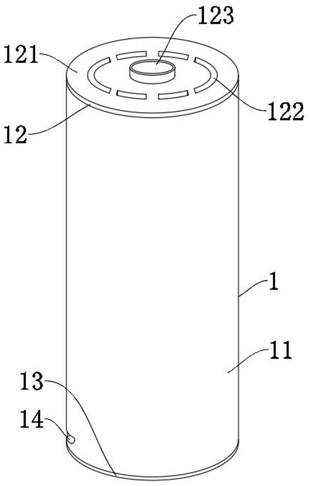
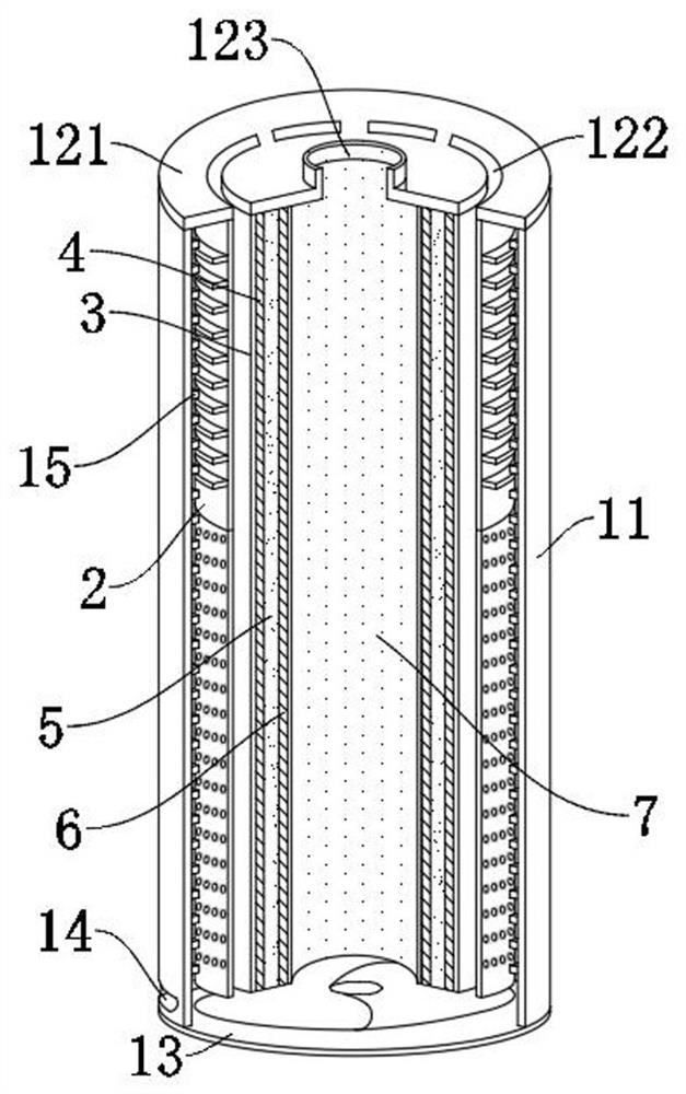
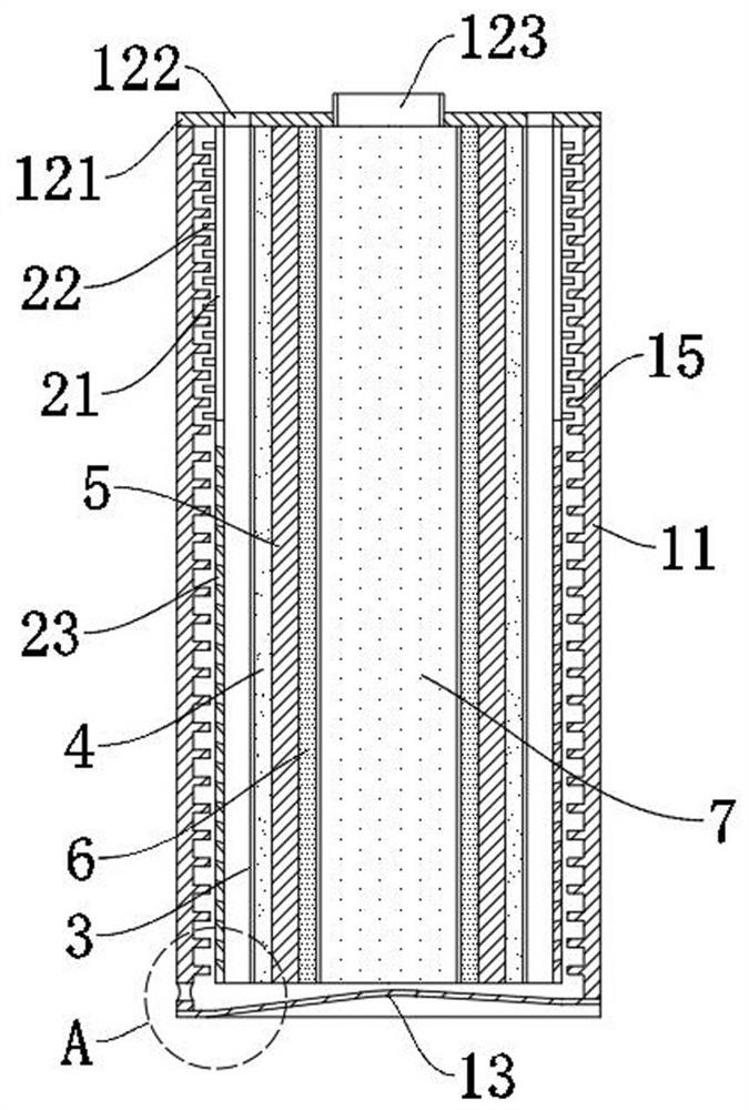
[0027] see Figure 1-Figure 5 , a tubular solid oxide fuel cell structure provided by the present invention, comprising a casing 1, a cathode reaction layer 4, an electrolyte layer 5 and an anode reaction layer 6, the anode reaction layer 6 is cylindrical, and the electrolyte layer 5 is wrapped around the anode Outside the reaction layer 6, the cathode reaction layer 4 is wrapped on the outside of the electrolyte layer 5, and the cathode reaction layer 4 is arranged inside the shell 1, and the shell 1 includes a middle shell tube 11, an end cover 12 and a bottom cover 13, and the end cover 12 and the bottom cover 13 are respectively fixed on the upper and lower ends of the middle casing 11, and the inside of the anode reaction layer 6 is pasted with an anode support layer 7, which is made of a breathable and heat-resistant material, which is conducive to ventilation and heat dissipation, and the anode support layer 7 The surface is smooth, which is conducive to drainage. The o...

Embodiment 2

[0034] On the basis of Embodiment 1, the difference is that: the first support ring 15 is in a spiral shape (not shown), and the first support ring 15 is in a spiral shape, the air guide tube 22 cooperates with the first support ring 15, and the first support ring 15 and the air guiding cylinder 22 are designed to distribute spirally downward, so that the top waste heat is condensed at the entrance due to the heat absorption of the reaction, and the generated water vapor can flow downward through the spirally downward first support ring 15 and the air guiding cylinder 22, and the drainage effect is better.

Embodiment 3

[0036] On the basis of Embodiment 1, the difference is that the cover body 121 is a hollow structure (not shown), and the inner cavity of the cover body 121 communicates with the heat recovery cavity, so that waste heat is more conducive to converging around the fuel adding tank 123, and more It is beneficial to provide heat for the reaction at the entrance of the fuel adding tank 123 and prevent supercooling.


PUM


Abstract

The invention relates to the technical field of fuel cells, in particular to a tubular solid oxide fuel cell structure, including a casing, a cathode reaction layer, an electrolyte layer and an anode reaction layer, the casing includes a middle casing, an end cover and a bottom cover. The end cover and the bottom cover are respectively fixed on the upper and lower ends of the middle casing, and the inside of the anode reaction layer is pasted with an anode support layer, the anode support layer is made of a breathable and heat-resistant material, and the anode support layer The surface of the cathode reaction layer is smooth, the outer surface of the cathode reaction layer is wrapped with a cathode support layer, the material of the cathode support layer is the same as that of the anode support layer, a support cylinder is fixed inside the middle shell, and the support cylinder and the middle shell A heat recovery chamber is formed between the cylinders, an air chamber is formed between the support cylinder and the cathode support layer, and the bottom of the anode support layer communicates with the heat recovery chamber. The invention is provided with a heat recovery cavity, which solves the problem of overcooling of the inlet without loss, improves the power generation capacity of the electric stack with the same volume, and increases the strength of the tubular electric stack at the same time.

Description

technical field [0001] The invention relates to the technical field of fuel cells, in particular to a tubular solid oxide fuel cell structure. Background technique [0002] The fixed oxide fuel cell is called the third-generation fuel cell, and mainly consists of four functional components, the cathode, the anode, the electrolyte and the connecting body, which are connected in series to form a stack with a rated power generation capacity. [0003] Tubular solid oxide fuel cells usually adopt an integrated structure. Taking methane fuel as an example, the methane reforming reaction often reacts violently in the inlet section, accompanied by the absorption of a large amount of heat, while the water vapor reforming reaction in the second half of the battery releases heat. The temperature presents a distribution situation in which both ends are high and the inlet temperature is low, that is, the supercooling effect. The supercooling effect will cause an axial temperature gradie...

Claims


Application Information

Patent Timeline
Patent Type & Authority Patents(China)
IPC IPC(8): H01M8/1213H01M8/1231H01M8/243H01M8/2475H01M8/04007H01M8/04014
CPCH01M8/1213H01M8/1231H01M8/243H01M8/2475H01M8/04007H01M8/04014H01M2008/1293Y02E60/50
Inventor 钱黎超秦刚华寿春暉
Owner CEMT CO LTD
Why Eureka
Try Eureka