
A non-reference clock frequency detection circuit with adjustable jitter tolerance

A frequency detection circuit and reference clock technology, applied in the field of communication systems, can solve the problems of narrow frequency capture range, unable to meet the requirements of communication systems, etc., and achieve the effect of adjustable jitter tolerance

Active Publication Date: 2022-06-28
苏州瀚宸科技有限公司
View PDF0 Cites 0 Cited by
  • Summary
  • Abstract
  • Description
  • Claims
  • Application Information

AI Technical Summary

Problems solved by technology

Phase-locked loop (PLL) is widely used in CDR circuit design, but its own narrow frequency capture range cannot meet the requirements of communication systems

Method used


Image

  • A non-reference clock frequency detection circuit with adjustable jitter tolerance
  • A non-reference clock frequency detection circuit with adjustable jitter tolerance
  • A non-reference clock frequency detection circuit with adjustable jitter tolerance

Examples


Embodiment Construction

[0042] In order to make the purposes, technical solutions and advantages of the embodiments of the present application more clear, the technical solutions in the embodiments of the present application will be described clearly and completely below with reference to the drawings in the embodiments of the present application. Obviously, the described embodiments It is a part of the embodiments of the present application, but not all of the embodiments. Based on the embodiments in the present application, all other embodiments obtained by those of ordinary skill in the art without creative efforts shall fall within the protection scope of the present application.

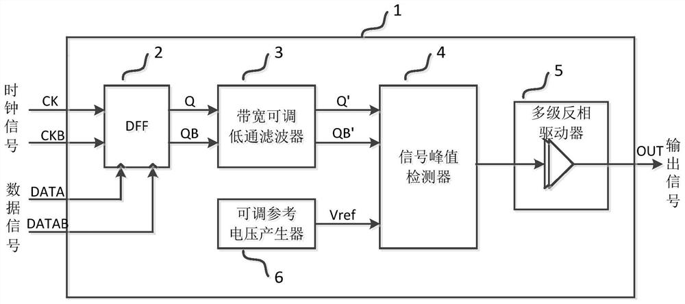
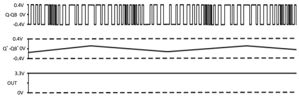
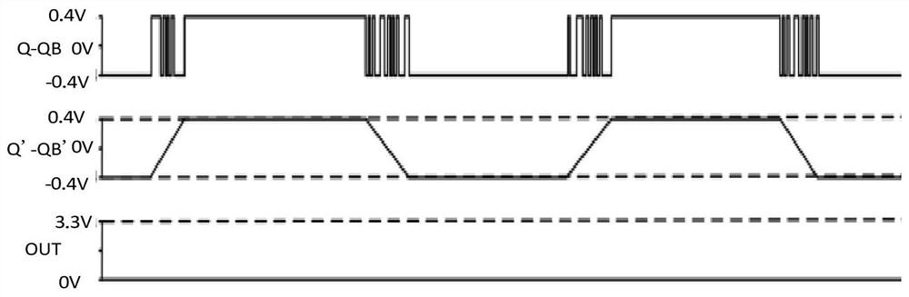
[0043] The embodiment of the present invention provides a reference-free clock frequency detection circuit with adjustable jitter tolerance, which has the function of detecting the difference between the frequency of the clock signal and the symbol rate of the input signal. When the difference is large, the frequency d...


PUM


Abstract

The invention discloses a non-reference clock frequency detection circuit with adjustable jitter tolerance, comprising: a data signal port of a D flip-flop receives differential clock signals CK and CKB, and a clock input port of the D flip-flop receives a differential input signal DATA and DATAB; the output of the D flip-flop produces output signals Q and QB, which are connected to the input of a low-pass filter which produces low-pass filtered output signals Q' and QB'; signal peak The first input end of the detection circuit is connected to the output end of the low-pass filter, the second input end of the signal peak detection circuit is connected to the output end of the reference voltage generator, and receives the reference voltage Vref; the signal peak detection circuit according to The signal peak values ​​of the Q' and QB' and the magnitude of the reference voltage Vref are output as digital signals.

Description

technical field [0001] The invention relates to the field of communication systems, in particular to a reference-free clock frequency detection circuit with adjustable jitter tolerance. Background technique [0002] In high-speed wired communication systems, in order to reduce costs, the data transmitted between the transmitter and the receiver is usually sent and received without a clock signal. For example, in optical communication, high-speed data is transmitted and received without a clock signal. In this case, the receiver is required to have a reference-less clock and data recovery circuit (Reference-less CDR). [0003] The clock and data recovery circuit has the following functions: recover the clock synchronized with the frequency and phase of the received signal from the data without the accompanying clock; recover the data from the data without the accompanying clock, reduce the signal jitter and improve the signal quality. Phase Locked Loop (PLL) is widely used ...

Claims


Application Information

Patent Timeline
Patent Type & Authority Patents(China)
IPC IPC(8): H03L7/091H03L7/18
CPCH03L7/091H03L7/18
Inventor 洪芃力
Owner 苏州瀚宸科技有限公司
Features
  • Generate Ideas
  • Intellectual Property
  • Life Sciences
  • Materials
  • Tech Scout
  • Unparalleled Data Quality
  • Higher Quality Content
  • 60% Fewer Hallucinations
Learn More