
Optical fiber external structure of laser cutting machine

A laser cutting machine and optical fiber technology, applied in laser welding equipment, welding equipment, metal processing equipment, etc., can solve the problems of optical fiber binding, long time, increased work content of replacing optical fibers, etc., and achieve the effect of improving efficiency and speed

Active Publication Date: 2021-10-08
PENTA CHUTIAN LASER (WENZHOU) CO LTD
View PDF7 Cites 0 Cited by
  • Summary
  • Abstract
  • Description
  • Claims
  • Application Information

AI Technical Summary

Problems solved by technology

And in the current situation, the optical fiber is generally placed inside the carrier, so that when the cutting head is maintained, it takes a lot of time to disassemble the optical fiber, thus affecting the maintenance efficiency of the cutting head
[0003] In order to overcome the above problems, the external processing of the optical fiber is realized by fixing the buckle at the outer end of the joist, thereby reducing the time consumed when removing the optical fiber, and further The maintenance rate of the cutting head has been improved, but the current external buckle basically can only bind the fiber of a single diameter, so when changing the type of fiber, it is necessary to replace the buckle that is compatible with the fiber type. This increases the work content when replacing the optical fiber and reduces the replacement rate of the optical fiber

Method used


Image

  • Optical fiber external structure of laser cutting machine
  • Optical fiber external structure of laser cutting machine
  • Optical fiber external structure of laser cutting machine

Examples


Embodiment Construction

[0026] The specific embodiments provided by the present invention will be described in detail below in conjunction with the accompanying drawings.

[0027] The reference signs and components involved in the accompanying drawings are as follows:

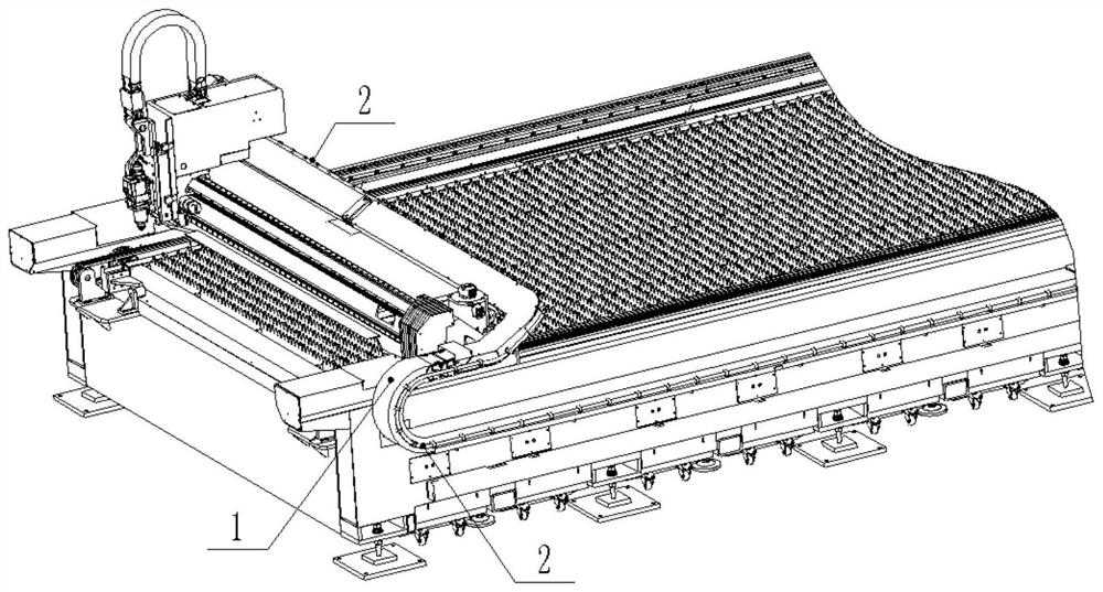
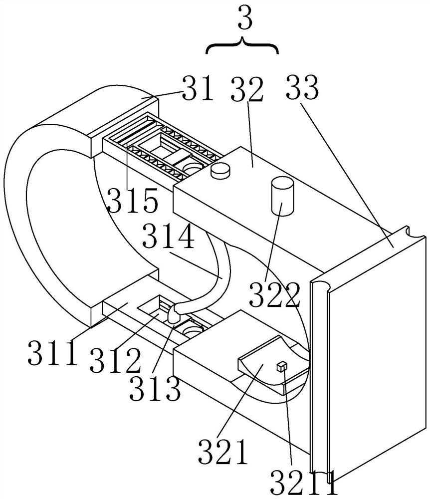
[0028] An external optical fiber structure of a laser cutting machine according to the present invention, specifically, the space inside the external external buckle can be changed through the moving plate in the external buckle, and then different types of optical fibers can be restrained, thereby avoiding the need to replace the optical fiber At the same time, an additional replacement of the external buckle occurs, thereby improving the efficiency of optical fiber replacement.

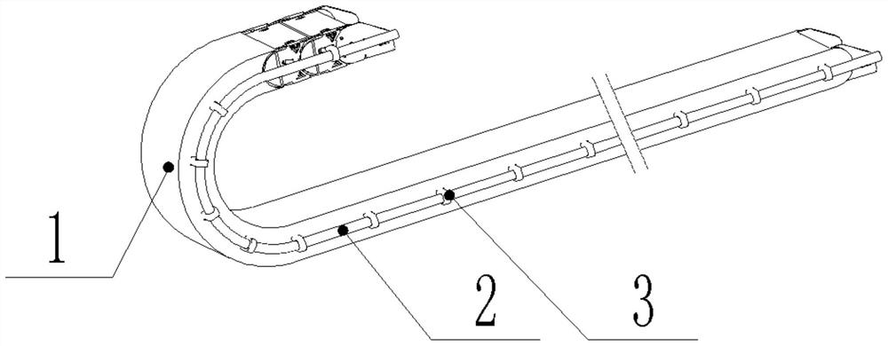
[0029] Such as Figure 1-Figure 7 As shown, a laser cutting machine optical fiber external structure, including a carrier 1, an optical fiber 2 and an external buckle 3 for binding the optical fiber, the carrier 1 is located on one side of the body, and th...


PUM


Abstract

The invention relates to an optical fiber external structure of a laser cutting machine. The structure comprises a bearing part, an optical fiber and an external buckle, wherein the bearing part is located on one side of a machine body, the external buckle is connected to the side, away from the machine body, of the bearing part, the optical fiber is bound by the external buckle, and the external buckle comprises a fixing clamping plate, a concave cavity for limiting an optical fiber is formed in the fixed clamping plate, and two movable plates are arranged in the concave cavity of the fixed clamping plate in a sliding manner. According to the invention, the external buckle is connected with the bearing part, so that the optical fiber is arranged externally, and the size of the space for constraining the optical fiber can be changed through the moving plate arranged in the fixed clamping plate, so that the optical fibers with different diameters are constrained, and the situation that the external buckle needs to be additionally replaced when the model of the optical fiber is replaced is avoided, and therefore, the replacement speed of the optical fiber is improved.

Description

【Technical field】 [0001] The invention relates to laser processing equipment, in particular to a laser cutting machine optical fiber external structure. 【Background technique】 [0002] Currently, when people disassemble and maintain the head of a laser cutting machine, it is often necessary to remove the optical fiber together with the cutting head. And under the current situation, the optical fiber is generally placed inside the carrier, so that when the cutting head is maintained, it takes a lot of time to disassemble the optical fiber, thereby affecting the maintenance efficiency of the cutting head. [0003] In order to overcome the above problems, the external processing of the optical fiber is realized by fixing the buckle at the outer end of the joist, thereby reducing the time consumed when removing the optical fiber and improving the maintenance speed of the cutting head. However, the current external The buckle basically can only bind the fiber of a single diamete...

Claims


Application Information

Patent Timeline
Patent Type & Authority Applications(China)
IPC IPC(8): B23K26/38B23K26/70
CPCB23K26/38B23K26/702
Inventor 布拉玛奇.马丁杨忠明胡鸽李永军李雪香康骐牛亭
Owner PENTA CHUTIAN LASER (WENZHOU) CO LTD
Learn More