Flame restriction strengthening device and method based on magnetic confinement and application

A technology of strengthening device and magnetic restraint, applied in lighting and heating equipment, combustion equipment, etc., can solve the problems of difficult burning intensity, unsafe refractory materials, and effectively restrain the flame.

Pending Publication Date: 2020-07-28
EAST CHINA UNIV OF SCI & TECH
View PDF0 Cites 4 Cited by
  • Summary
  • Abstract
  • Description
  • Claims
  • Application Information

AI Technical Summary

Problems solved by technology

[0006] The technical problem to be solved by the present invention is to overcome the inability of refractory materials to safely and effectively restrain the flame at high temperatures (the temperature of the outer flame of the flame is greater than 2200 ° C), and to increase

Method used


Image

  • Flame restriction strengthening device and method based on magnetic confinement and application
  • Flame restriction strengthening device and method based on magnetic confinement and application

Examples


Embodiment 1

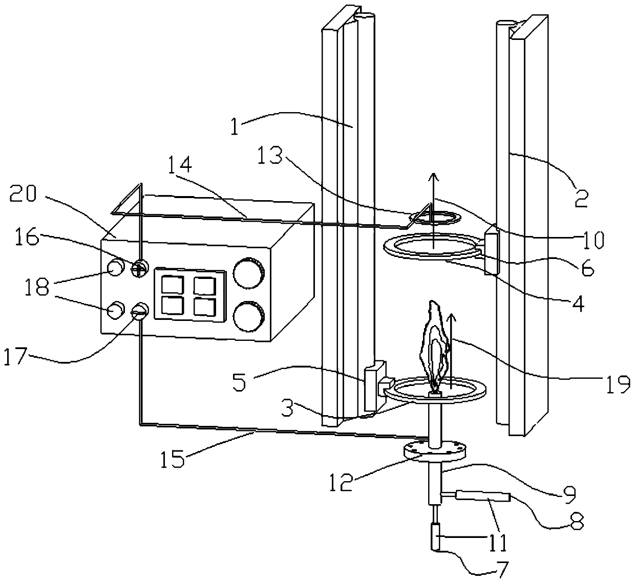
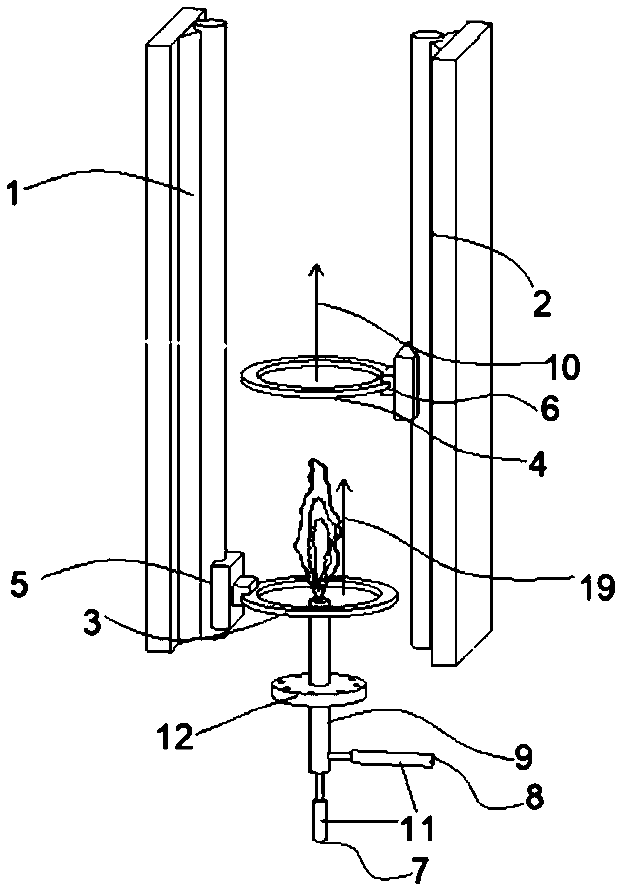
[0070] Such as figure 1 Shown is an embodiment of a combustion flame confinement enhancement device based on magnetic confinement. It includes the first guide rail 1 and the second guide rail 2 which are arranged oppositely, the first annular permanent magnet 3 (the magnetic poles are arranged in the following way: S pole to N pole from top to bottom along the central axis) and the second annular permanent magnet located above. Magnet 4 (the arrangement of magnetic poles is: S pole to N pole from top to bottom along the central axis), the first slider 5 and the second slider 6, which are arranged on the conductive magnetic pole in the area below the first annular permanent magnet 3 Nozzle 9 (in this embodiment, a nozzle with a stainless steel double channel structure), the nozzle 9 is provided with a nozzle insulating flange 12, and the nozzle insulating flange 12 made of polytetrafluoroethylene is connected to the nozzle bracket and kept insulated; There are nozzle inner cha...

Embodiment 2

[0077] The device in embodiment 1 is used to strengthen the confinement of the combustion flame. The molar flow ratio of methane gas and pure oxygen in the nozzle inner channel 7 and the nozzle outer channel 8 is 1:2, and an outer flame is formed at the outlet of the nozzle 9. Flames with temperatures up to 2850°C. The magnetic induction intensity of the magnetic mirror is the largest near the ring, about 0.05Wb / m2.

[0078] The nozzle 9 forms plasma in the high-temperature flame during the combustion process, and the flame enters the magnetic mirror formed by the magnetic fields of the first annular permanent magnet 3 and the second annular permanent magnet 4, and the plasma is bound by the magnetic field in the magnetic mirror to shuttle between the two permanent between the magnets, thereby forming a confinement of the burning flame. The spacing adjustment range of the first annular permanent magnet 3 and the second annular permanent magnet 4 is 600mm~30mm, and the adjustm...


PUM

PropertyMeasurementUnit
Lengthaaaaaaaaaa
Outer diameteraaaaaaaaaa
The inside diameter ofaaaaaaaaaa

Abstract

The invention discloses a flame restriction strengthening device and method based on magnetic confinement and application. The flame restriction strengthening device comprises a first guide rail and asecond guide rail. The first guide rail and the second guide rail are oppositely arranged. The adjustment of the vertical separation distance between a first annular permanent magnet and a second annular permanent magnet is achieved by the movement of the first annular permanent magnet and/or the second annular permanent magnet. According to the arrangement mode of the magnetic poles, the N polesand the S poles are arranged from top to bottom, or the S poles and the N poles are arranged from top to bottom. The first annular permanent magnet is located in the region arranged below the vertexof a flame formed in an outlet of a nozzle, and the second annular permanent magnet is located in the region arranged above the outlet of the nozzle. The flame restriction strengthening device furthercomprises a first conductor. The first conductor is located above the nozzle and connected with a positive electrode. The central axis of the nozzle penetrates through the annular region of the firstannular permanent magnet, the annular region of the second annular permanent magnet and the region defined by the first conductor, and is crossed with the first conductor. The flame restriction strengthening device and method based on magnetic confinement achieve the simple and effective strengthened restriction conducted by the magnetic field and the electric field on the high-temperature combustion flame.

Description

technical field [0001] The invention relates to a flame confinement strengthening device, method and application based on magnetic confinement. Background technique [0002] Magnetic confinement is one of the reaction process confinement methods based on the interaction between magnetic field and electrons. For a long time, magnetic confinement has made great progress in the application of atomic energy, especially for the plasma confinement of nuclear fusion. Scholars at home and abroad have carried out a lot of basic and applied research, and achieved considerable research and application results. [0003] Plasma is a state of matter under high temperature or specific excitation. It is a partially or completely ionized ionized gaseous substance, which is composed of a large number of charged particles (ions, electrons) and neutral particles (atoms, molecules). The temperature can be as high as tens of thousands of degrees. At present, plasma technology has been widely us...

Claims


Application Information

Patent Timeline
IPC IPC(8): F23C99/00
CPCF23C99/001
Inventor 龚岩郭庆华于广锁梁钦锋王辅臣陈雪莉刘海峰王亦飞代正华李伟锋郭晓镭许建良王兴军陆海峰赵辉刘霞丁路赵丽丽
Owner EAST CHINA UNIV OF SCI & TECH
Why Eureka
Try Eureka