Nanofluid MQL and Atomization Cooling Ultra-Precision Cutting Medium Supply System

A nano-fluid, micro-lubrication technology, used in grinding/polishing equipment, grinding/polishing safety devices, metal processing equipment, etc. Crack lubrication and other problems, to avoid the rupture of lubricating oil film and lubrication failure, avoid excessive heat generation, and improve the lubrication state.

Active Publication Date: 2022-07-15
YUNNAN KIRO CH PHOTONICS
View PDF19 Cites 0 Cited by
  • Summary
  • Abstract
  • Description
  • Claims
  • Application Information

AI Technical Summary

Problems solved by technology

[0014] This application provides a nanofluid micro-lubrication and atomization cooling ultra-precision cutting medium supply system, which can be used to solve the problem of poor cooling effect of the micro-lubrication device in the prior art, which cannot effectively reduce the temperature of the cutting zone; the cooling effect is uneven, Lead to lubricant film breakage and lubrication failure; difficulty in determining optimal lubricant dosage leading to technical problems of insufficient lubrication

Method used


Image

  • Nanofluid MQL and Atomization Cooling Ultra-Precision Cutting Medium Supply System
  • Nanofluid MQL and Atomization Cooling Ultra-Precision Cutting Medium Supply System
  • Nanofluid MQL and Atomization Cooling Ultra-Precision Cutting Medium Supply System

Examples


Embodiment 1

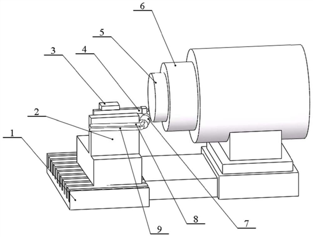
[0079] The application provides a nanofluid micro-lubrication and atomization cooling ultra-precision cutting medium supply system, including: a workbench 1, a compressed air gas path 9, a nanofluid liquid path 8, a tool 4, a workpiece to be processed 5, and jet atomization Nozzle 7; tool 4 and workpiece 5 to be processed are arranged on the worktable 1, and move toward or away from each other; the jet atomization nozzle 7 is arranged on one side of the tool 4, and the second end of the jet atomization nozzle 7 faces the tool 4 and the The cutting area contacted by the workpiece 5 to be processed is set; the worktable 1 used in the present application and this embodiment can be a commonly used worktable. The specific structure is not exhaustive.

[0080] The compressed air gas path 9 and the nano-fluid liquid path 8 are respectively connected to the first end of the jet atomization nozzle 7 for feeding;

[0081] The second end of the jet atomizing nozzle 7 sprays a three-phas...

Embodiment 2

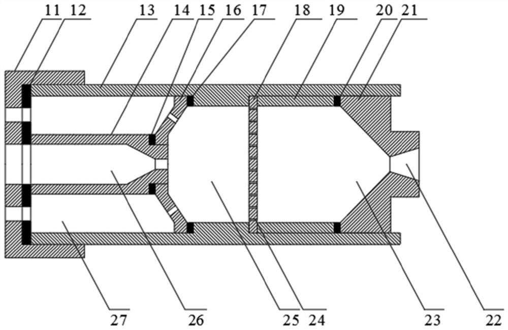
[0109] The difference between the spray head 21 used in this embodiment and Embodiment 1: as Figure 4 As shown in a, the included angle c shown in Fig. a is the included angle between the inner side wall of the nozzle outlet 22 and the extension line of the feed aperture, and the included angle c is defined the same in other embodiments; the cross-section of the acceleration section 23 used in this embodiment is the same. It is a trapezoid; the included angle c in the cross section of the nozzle outlet 22 is 10~15°.

[0110] Other differences between this embodiment and Embodiment 1: the angle between the extension line of the central axis of the jet atomizing nozzle 7 and the machining end face of the workpiece 5 to be machined is β, and the angle of β is 35°; the spray end face of the jet atomizing nozzle 7 and the tool 4. The distance d between the cutting tip and the contact point of the workpiece 5 to be processed is 5 cm; the jet flow rate of the jet atomizing nozzle 7 ...

Embodiment 3

[0112] The difference between the spray head 21 used in this embodiment and Embodiment 1: as Figure 4 As shown in b, the cross-section of the acceleration section 23 is a trapezoid, and the bottom surface of the trapezoid is provided with a connecting structure with a rectangular cross-section; the included angle c is 15-30°.


PUM


Abstract

The present application discloses a nanofluid micro-lubrication and atomization cooling ultra-precision cutting medium supply system, comprising: a workbench, a compressed air path, a nanofluid liquid path, a tool, a workpiece to be processed, and a jet atomization nozzle; The workpiece to be processed is set on the worktable, and moves toward or away from each other; the jet atomization nozzle is arranged on one side of the tool, and the second end of the jet atomization nozzle is arranged towards the cutting area where the tool contacts the workpiece to be processed; the jet atomization nozzle The second end of the jet sprays a three-phase bubble-like flow to the cutting area at a near-sonic speed. By setting the jet atomization nozzle, the high-speed atomization of the nano-fluid can be realized by using compressed air, so that a large number of tiny droplets are formed after spraying, which are evenly attached to the cutting surface of the cutting area, thereby effectively solving the problem of direct nano-fluid directly. Technical problems when used for cutting.

Description

technical field [0001] The application relates to the technical field of ultra-precision cutting, in particular to a nano-fluid micro-lubrication and atomization cooling ultra-precision cutting medium supply system. Background technique [0002] Because the cutting objects are mostly difficult-to-machine materials, such as anisotropic composite materials, infrared optical hard and brittle materials, etc., a large amount of heat will be generated during the cutting process. Since the material layer to be cut is relatively thin, most of the heat is transmitted. When entering the workpiece, only a small part of the heat is taken away by the chips. The heat introduced into the workpiece will adversely affect the ultra-precision cutting process, resulting in pitting, pits, cracks, and surface / subsurface damage on the machined surface. Defects, reducing the service life and working reliability of the parts, but also aggravating the wear of the tool and affecting the service life o...

Claims


Application Information

Patent Timeline
Patent Type & Authority Patents(China)
IPC IPC(8): B24B55/03
CPCB24B55/03
Inventor 康杰王元康张万清杨伟声程海娟邱红方肖建国刘亚飞刘尧邹俊东魏奇鲁延栾博良翟常丽
Owner YUNNAN KIRO CH PHOTONICS
Why Eureka
Try Eureka