
Stay wire binding wire manufacturing device

A technology for manufacturing devices and controllers, which is applied in the directions of transportation and packaging, delivery of filamentous materials, thin material processing, etc. It can solve problems such as uneven size of binding wire loops, inconvenient operation, economic losses of production enterprises and power enterprises, and achieve Improve work efficiency and process quality, facilitate operation and portability, and reduce work intensity

Pending Publication Date: 2021-10-08
KUYTUN POWER SUPPLYING CO STATE GRID XINJIANG ELECTRIC POWER CO
View PDF0 Cites 1 Cited by
  • Summary
  • Abstract
  • Description
  • Claims
  • Application Information

AI Technical Summary

Problems solved by technology

In the actual installation and construction of overhead transmission lines, due to their wide distribution area and complex environment, if the transmission line causes a power outage in a large area of ​​power supply due to tilted towers, broken poles or fallen towers, it will not only bring people It will bring great inconvenience to daily life, and will also cause huge economic losses to some production enterprises and electric power enterprises, seriously affecting the stability and harmony of the society.
Therefore, in order to strengthen the protection of towers and lines and reduce the risk of power outages in transmission line infrastructure construction, inspection and maintenance work, it is often necessary to install guy wires on towers or wires at crossarms or insulator hanging points, etc. The wire (iron wire) is very inconvenient to operate in the process of binding and pulling the wire because of its long length, so it is necessary to wind the binding wire into a circle in the early stage of work, which is not only convenient to carry, but also convenient to bind and pull the wire; The problems in the process include: (1) the bare-handed hemp hoop is easy to cause hand pain, and the size of the wrapped binding wire loop is uneven and has many concave and convex points; Binding wires are prone to rust. Therefore, using the existing manual winding method of binding wires is not only time-consuming and laborious, but also the binding wire loops are not round and smooth enough, and there are many inflection points. In actual binding, it will not only lead to low work efficiency, but also It will lead to problems such as rough wire binding process

Method used


Image

  • Stay wire binding wire manufacturing device
  • Stay wire binding wire manufacturing device
  • Stay wire binding wire manufacturing device

Examples


Embodiment 1

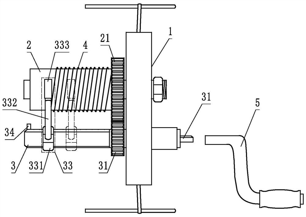
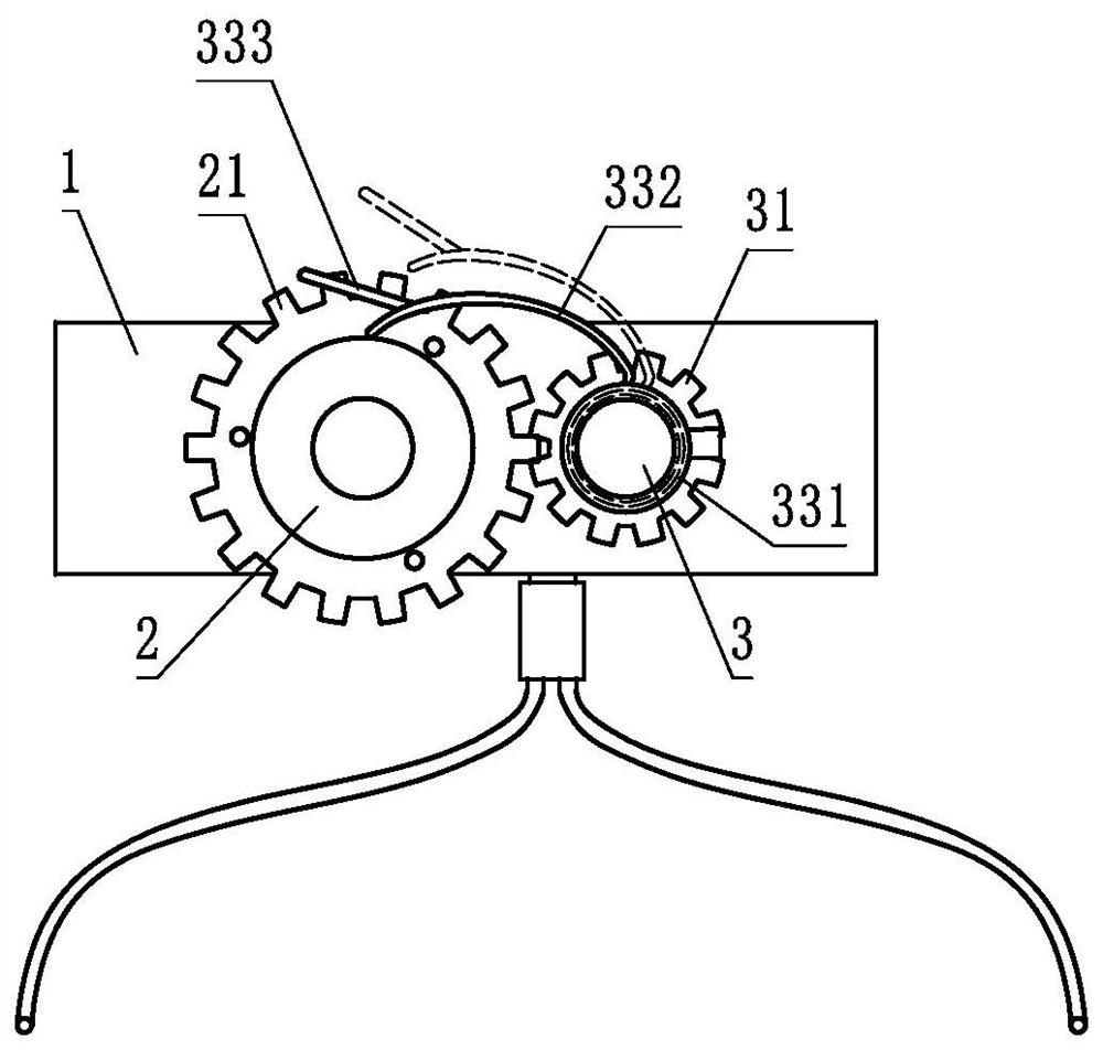
[0034] This embodiment provides a device for making a pulling wire binding wire, see Figure 1-2, the device includes a fixing base 1. In this embodiment, the fixing base 1 includes a supporting foot frame and a long fixing bracket. The fixing bracket is laterally fixed on the supporting foot frame, and the fixing bracket is provided with a winding roller 2 and Limiting roller 3, the winding roller 2 and the limiting roller 3 are arranged side by side and are both perpendicular to the fixing bracket, that is, one end of the winding roller 2 and the limiting roller 3 is fixed on the fixing bracket, and the winding roller 2 and The limit roller 3 is respectively provided with a gear A21 and a gear B31 at one end close to the fixed bracket. The gear A21 and the gear B31 mesh with each other. The limit roller 3 is provided with a limit component 33, which can be opposite to the limit roller 3. Move and its free end can be in contact with the take-up roller 2 or its free end can be...

Embodiment 2

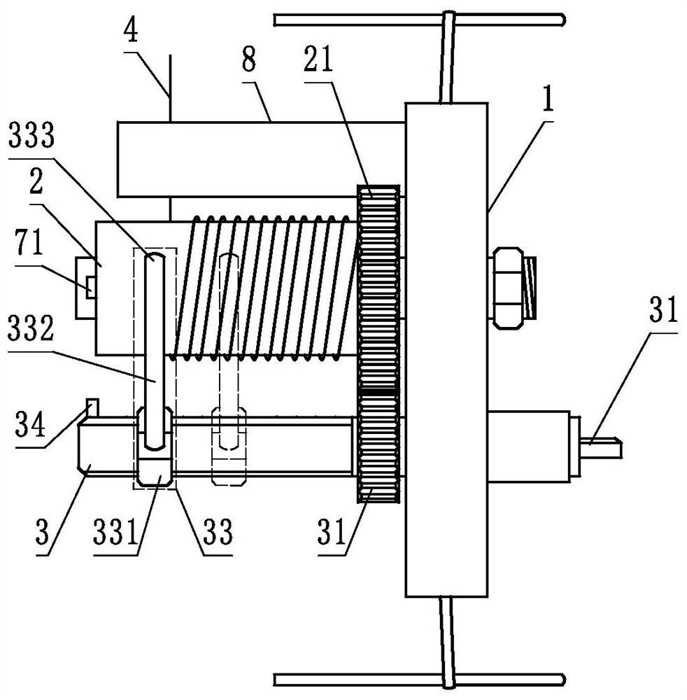
[0040] Compared with Embodiment 1, the difference of this embodiment is that a counting assembly is provided, and the power mechanism is a motor. The counting assembly includes an encoder 71 and a controller 72, see Figure 3-4 , in this embodiment, the controller 72 can be arranged on the fixed seat 1, the encoder 71 is arranged on one side of the winding roller 2 and can rotate with the winding roller 2, and the encoder 71 and the signal input of the controller 72 The motor is connected to the signal output end of the controller 72. When using, first set the required length parameters of the binding wire 4 in the controller 72 according to the needs. In this embodiment, it is preferable to set multiple sets of length parameters of the binding wire 4. The length parameters of the binding wire 4 correspond to different switching modes. In this way, it is convenient for the staff to operate and improve the production efficiency of the binding wire 4. At the same time, the corres...

Embodiment 3

[0044] Compared with the embodiment 1 or 2, the difference of this embodiment is that the winding roller 2 is provided with a wire withdrawal assembly 9, the wire withdrawal assembly 9 includes an outer sleeve 91 and an inner sleeve 92, and the outer sleeve 91 is provided with a spring. Tube 93, the inner sleeve 92 is nested in the outer sleeve 91 and can be telescopically moved in the outer sleeve 91 under the action of the spring tube 93. In this embodiment, in order to fix the state of the inner sleeve 92 in the outer sleeve 91, To avoid its rotation, preferably the inner sleeve 92 and the outer sleeve 91 are connected by a spring tube 93; the outer sleeve 91 is provided with a plurality of through holes 911, and the inner sleeve 92 is provided with a resilient connecting rod 921, the connecting rod 921 One end is provided with a protrusion 922, and the protrusion 922 can expand and contract in the through hole 911 of the outer sleeve 91. In this embodiment, preferably, two ...


PUM


Abstract

The invention discloses a stay wire binding wire manufacturing device which comprises a fixing base. A winding roller and a limiting roller which are arranged side by side are arranged on the fixing base, a gear A and a gear B are arranged on the winding roller and the limiting roller respectively and mesh with each other, and a limiting assembly is arranged on the limiting roller. The limiting assembly can move relative to the limiting roller, the free end of the limiting assembly can be in contact with the winding roller or the free end of the limiting assembly can be close to the winding roller, and a driving shaft is arranged at one end of the winding roller or one end of the limiting roller and can be connected with a power mechanism and driven by a power mechanism to drive the winding roller and the limiting roller to rotate. By means of the device, a binding wire can be rapidly wound, and wound binding wire rings are uniform in size, round and smooth.

Description

technical field [0001] The invention relates to a device for making a pull wire binding wire. Background technique [0002] Overhead transmission lines are a vital part of the power system and the main means of power transportation. In the actual installation and construction of overhead transmission lines, due to their wide distribution area and complex environment, if the transmission line is powered by a large area of ​​power supply area due to the tilt, broken pole or collapsed tower of the transmission line, it will not only give people It will bring great inconvenience to the daily life of some production enterprises and electric power enterprises, and will seriously affect the stability and harmony of society. Therefore, in order to strengthen the protection of towers and lines and reduce the risk of power outages in the infrastructure construction, maintenance and repair of transmission lines, it is often necessary to install pull wires on the towers or conductors a...

Claims


Application Information

Patent Timeline
Patent Type & Authority Applications(China)
IPC IPC(8): B65H54/547B65H54/44B65H54/70B65H61/00B65H67/04B21F11/00B21F1/02
CPCB65H54/547B65H54/44B65H54/70B65H61/00B65H67/0411B21F11/00B21F1/023B21F1/026B65H2701/36B65H2301/417
Inventor 史光举赵一鑫
Owner KUYTUN POWER SUPPLYING CO STATE GRID XINJIANG ELECTRIC POWER CO
Learn More