Cast iron blast furnace

A blast furnace and cast iron technology, applied in blast furnaces, blast furnace details, blast furnace parts and other directions, can solve the problems of reducing the fuel delivery rate, difficult to transport, falling on the ground, etc., to improve the transport efficiency, ensure smooth operation, and increase stability. Effect

Active Publication Date: 2021-10-08
日照铸福实业有限公司
View PDF6 Cites 0 Cited by
  • Summary
  • Abstract
  • Description
  • Claims
  • Application Information

AI Technical Summary

Problems solved by technology

[0005] The main purpose of the present invention is to provide a cast iron blast furnace, which can effectively solve the problem that the lumpy fuel is easy to roll and slide on the surface of the conveyor belt during the fuel transportation process, and it is not easy to Transportation, and when part of the powder fuel is sticky due to moisture, it is easy to stick to the surface of the conveyor belt, reducing the fuel delivery rate, and the fuel sticking to the surface of the conveyor belt will fall to the ground under the action of gravity when the conveyor belt rotates to the bottom, resulting in waste of fuel The problem

Method used


Image

  • Cast iron blast furnace
  • Cast iron blast furnace
  • Cast iron blast furnace

Examples


Embodiment Construction

[0024] In order to make the technical means, creative features, goals and effects achieved by the present invention easy to understand, the present invention will be further described below in conjunction with specific embodiments.

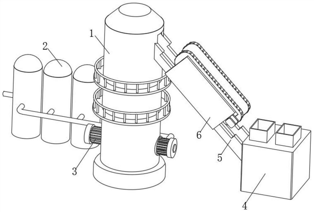
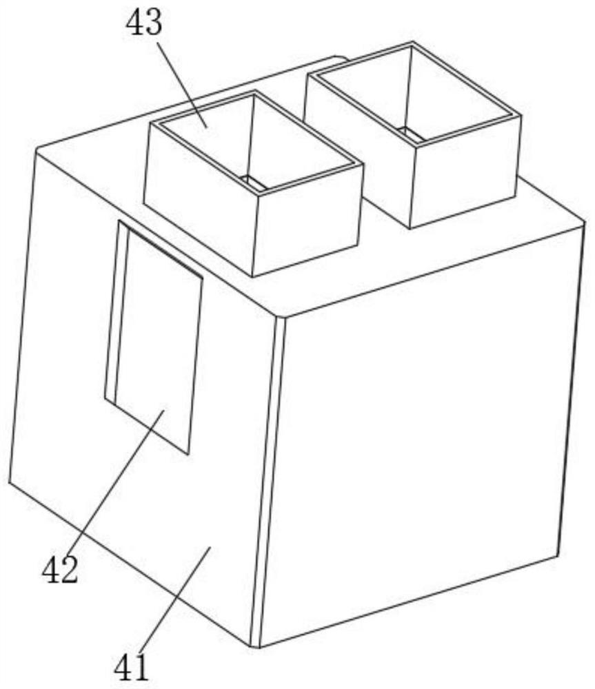
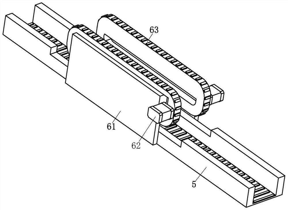
[0025] Such as Figure 1-5 As shown, a cast iron blast furnace includes a blast furnace body 1, a blower 3 is arranged on the surface of the blast furnace body 1, a blast furnace 2 is arranged on one side of the blast furnace body 1, and a charging box 4 is arranged on the other side of the blast furnace body 1, and the charging box 4 is arranged on the other side of the blast furnace body 1. The box 4 includes a box body 41. One end of the box body 41 is provided with a discharge port 42. A feeding device 5 is arranged between the blast furnace body 1 and the charging box 4. The front end of the feeding device 5 is provided with a suspension circulation movement device 6. The suspension circulation Motion device 6 comprises fixed plate 61, and on...


PUM


Abstract

The invention relates to the technical field of cast iron, in particular to a cast iron blast furnace. The cast iron blast furnace comprises a blast furnace body, wherein an air blower is arranged on the surface of the blast furnace body; a blast furnace is arranged at one side of the blast furnace body; a feeding box is arranged at the other side of the blast furnace body, and the feeding box comprises a box body; a discharge hole is formed in one end of the box body; a feeding device is arranged between the blast furnace body and the feeding box; a suspended circulating motion device is arranged at the front end of the feeding device and comprises a fixing plate; a motor is arranged at one end of the fixing plate; a conveyor belt is connected to the rear end of the fixing plate; a pushing device is arranged on the surface of the conveyor belt, and the pushing device comprises a connecting plate; and a screw is movably connected to the interior of the connecting plate. According to the cast iron blast furnace, fuel can be prevented from being stacked and adhered to the surface of the feeding conveyor belt, waste of the fuel is reduced, and round-block-shaped fuel can be prevented from sliding down, so that the feeding efficiency is high.

Description

technical field [0001] The invention relates to the technical field of cast iron, in particular to a cast iron blast furnace. Background technique [0002] Cast iron blast furnace is a kind of equipment that uses coke, iron-containing ore and flux to continuously produce liquid pig iron in the blast furnace. It is an important link in modern iron and steel production. The process is relatively simple, the output is large, the labor productivity is high, and the energy consumption is low. main method of [0003] The invention patent with the patent number of 2018115481676 discloses a blast furnace ironmaking equipment, which includes an inner layer furnace body, an outer layer furnace body for forming a furnace cavity for ironmaking with the inner layer furnace body, a bottom plate and several sets respectively Air supply components at the lower part of the inner furnace body and the lower part of the outer furnace body. The blast furnace ironmaking equipment provided by th...

Claims


Application Information

Patent Timeline
IPC IPC(8): C21B7/00B65G19/04B65G19/20B65G19/24B65G21/20B65G45/10B65G47/18
CPCC21B7/00B65G19/04B65G19/20B65G19/24B65G47/18B65G45/10B65G21/2081
Inventor 沈国扬郑东风
Owner 日照铸福实业有限公司
Why Eureka
Try Eureka