
Prefabricated concrete main beam and cast-in-place secondary beam connecting structure and construction method thereof

A prefabricated concrete and connection structure technology, applied in the direction of structural elements, building components, building structures, etc., can solve the problem of low node strength at the junction of prefabricated main beams and cast-in-place secondary beams, which cannot effectively prevent the stress concentration of cast-in-place secondary beams, The low structural strength of the primary and secondary beam joints achieves the effect of convenient and quick binding, which is conducive to hoisting operations and reduces the difficulty of transportation

Pending Publication Date: 2021-10-08
CHINA FIRST METALLURGICAL GROUP
View PDF2 Cites 0 Cited by
  • Summary
  • Abstract
  • Description
  • Claims
  • Application Information

AI Technical Summary

Problems solved by technology

Although the connection structure is relatively simple when hoisting the prefabricated main beam, the structural strength at the joint of the primary and secondary beams is low, and the bending and shearing resistance is poor, which cannot effectively prevent the stress concentration of the cast-in-place secondary beam in the connection area. Causes oblique cracks, affecting load performance and building quality
[0004] In the prior art, it is very difficult to bind the secondary beam steel bars at the junction of the prefabricated main beam and the cast-in-place secondary beam. A long groove is reserved in advance on the prefabricated laminated main beam at the intersection to meet the anchorage requirements of the cast-in-place secondary beam bent anchor reinforcement at the junction, and the post-casting section is finally poured, but it is limited by the width of the prefabricated main beam , so that the width of the slot is too small, and it is difficult to vibrate and compact the post-cast concrete at this position, which eventually leads to low joint strength at the junction of the prefabricated main beam and the cast-in-place secondary beam

Method used


Image

  • Prefabricated concrete main beam and cast-in-place secondary beam connecting structure and construction method thereof
  • Prefabricated concrete main beam and cast-in-place secondary beam connecting structure and construction method thereof

Examples


Embodiment Construction

[0031] The present invention will be further described below in conjunction with accompanying drawing.

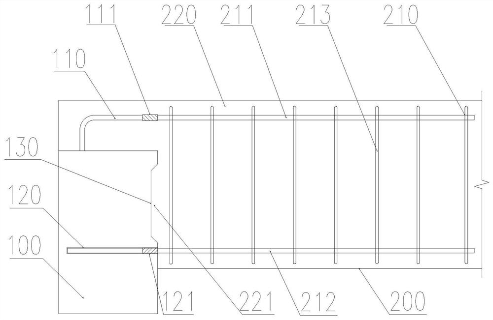
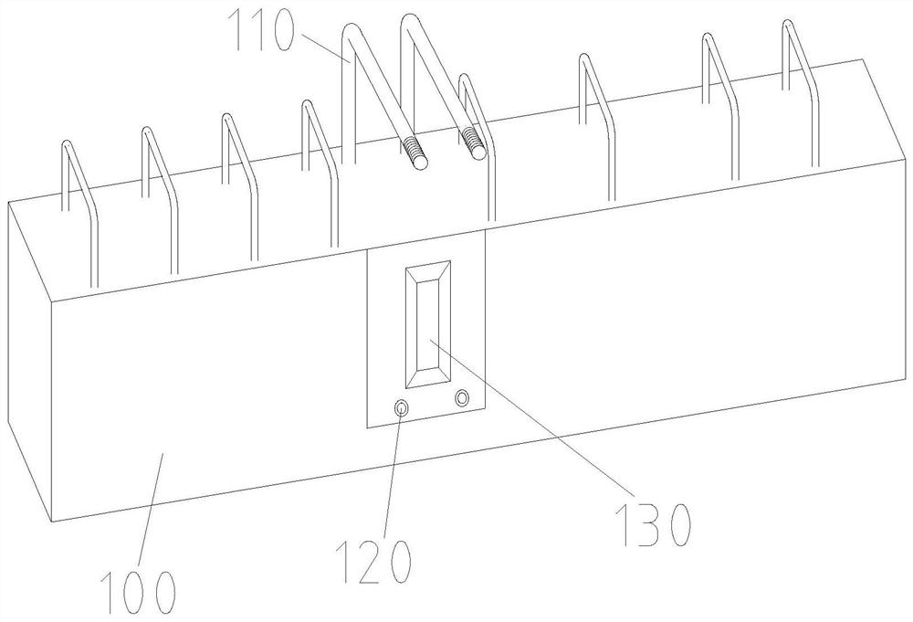
[0032] as attached figure 1 , figure 2 As shown, a prefabricated concrete main beam and cast-in-place secondary beam connection structure, including:

[0033] The prefabricated concrete main beam 100 has an installation position on it, a bent anchor steel bar 110 is installed on the top wall of the installation position, and a pre-embedded hole 120 is opened on the side wall of the installation position, and a pre-embedded hole 120 is provided in the pre-embedded hole 120. Straight thread sleeve 121;

[0034] The cast-in-place secondary beam 200, which is installed at the installation position, the cast-in-place secondary beam 200 includes a steel bar skeleton 210 and cast-in-place concrete 220, and the upper longitudinal reinforcement 211 connection end of the steel bar skeleton 210 is connected to the bent anchor bar 110 , the connection end of the lower longitudinal ...


PUM


Abstract

The invention provides a prefabricated concrete main beam and cast-in-place secondary beam connecting structure. The prefabricated concrete main beam and cast-in-place secondary beam connecting structure comprises a prefabricated concrete main beam and a cast-in-place secondary beam and a connecting piece, wherein the prefabricated concrete main beam is provided with a mounting position, a bent anchor steel bar is mounted on the top wall of the mounting position, a pre-buried hole is formed in the side wall of the mounting position, and a pre-buried straight thread sleeve is arranged in the pre-buried hole; the cast-in-place secondary beam is mounted at the mounting position, the cast-in-place secondary beam comprises a steel bar framework and cast-in-place concrete, the upper longitudinal bar connecting end of the steel bar framework is connected with the bent anchor steel bar, the lower longitudinal bar connecting end of the steel bar framework is provided with a lower bar external thread, the lower longitudinal bar connecting end is inserted into the pre-buried hole, and the lower bar external thread is in threaded connection with the pre-buried straight thread sleeve; the cast-in-place concrete wraps and fills the mounting position and the steel bar framework. According to the prefabricated concrete main beam and cast-in-place secondary beam connecting structure, the pre-buried straight thread sleeve is arranged on the side wall of the mounting position and connected with a lower longitudinal bar of the cast-in-place secondary beam, the bent anchor steel bar is pre-buried on the top wall of the mounting position, the straight section end of the bent anchor steel bar is connected with an upper longitudinal bar of the cast-in-place secondary beam, the connecting effect is guaranteed, and the cast-in-place secondary beam and the prefabricated concrete main beam form a stable whole.

Description

technical field [0001] The invention belongs to the technical field of assembled integral construction, and in particular relates to a connection structure between a prefabricated concrete main beam and a cast-in-place secondary beam and a construction method thereof. Background technique [0002] The key to the prefabricated integrated structure is how to effectively connect the prefabricated components made in the factory to form an overall structural system after being hoisted on site. Among them, for the connection structure of the prefabricated main beam and the cast-in-place secondary beam, the difficulty of installing the prefabricated main beam, the difficulty of binding the steel bars of the cast-in-place secondary beam, and the quality of concrete pouring at this node will directly affect the construction progress and quality of the project. Therefore, on the premise of ensuring the safety of the structure, it is an urgent problem to be solved in the engineering fi...

Claims


Application Information

Patent Timeline
Patent Type & Authority Applications(China)
IPC IPC(8): E04B1/20E04B1/21E04B1/41E04C5/16
CPCE04B1/20E04B1/21E04B1/4121E04C5/165
Inventor 琚明明车二平应浩赵强强胡峰
Owner CHINA FIRST METALLURGICAL GROUP
Learn More