Tunnel pipe shed grouting device and pressure-adjustable reverse reinforcement construction method

A technology of grouting device and construction method, applied in tunnels, earthwork drilling, mining equipment and other directions, can solve the problems of grouting, instability of the face, easy to block pipes, etc., to improve the quality of grouting and the diffusion distance. , the effect of strong diffusion

Pending Publication Date: 2021-10-08
CCCC SECOND HARBOR ENG +1
View PDF4 Cites 0 Cited by
  • Summary
  • Abstract
  • Description
  • Claims
  • Application Information

AI Technical Summary

Problems solved by technology

[0003] At present, the common mid-pipe shed grouting methods adopted at home and abroad will generate the greatest grout pressure at the tail of the mid-pipe shed (near the orifice), which is likely to cause secondary disturbances on the tunnel face, making the tunnel face unstable; and The cracks in the surrounding rock at the orifice are well developed, and the grout can easily seep into the adjacent grouting hole, causing the pipe to be blocked, making the grouting hole unable to carry out subsequent grouting
[0004] In order to solve the above problems, it is necessary to provide a new type of grouting device and grouting method, optimize the existing grouting method, and avoid the problems of uneven reinforcement and easy plugging during grouting

Method used


Image

  • Tunnel pipe shed grouting device and pressure-adjustable reverse reinforcement construction method
  • Tunnel pipe shed grouting device and pressure-adjustable reverse reinforcement construction method
  • Tunnel pipe shed grouting device and pressure-adjustable reverse reinforcement construction method

Examples


Embodiment Construction

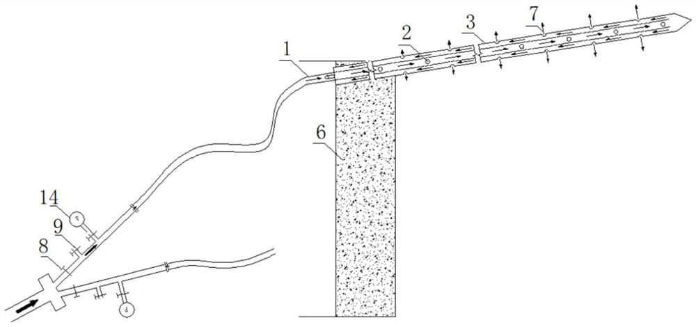
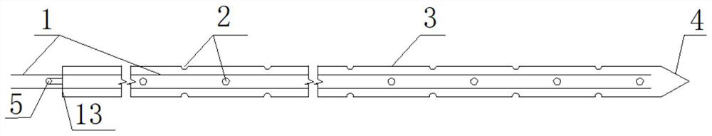
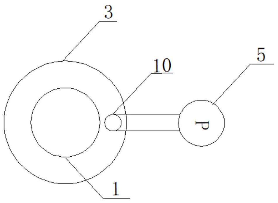
[0036] The present invention will be further described in detail below in conjunction with the accompanying drawings, so that those skilled in the art can implement it with reference to the description.

[0037] It should be noted that the experimental methods described in the following embodiments, unless otherwise specified, are conventional methods, and the reagents and materials, if not otherwise specified, can be obtained from commercial sources; in the description of the present invention, The terms "landscape", "portrait", "top", "bottom", "front", "rear", "left", "right", "vertical", "horizontal", "top", "bottom", The orientation or positional relationship indicated by "inner", "outer", etc. is based on the orientation or positional relationship shown in the drawings, which is only for the convenience of describing the present invention and simplifying the description, and does not indicate or imply that the referred device or element must have Certain orientations, co...


PUM


Abstract

The invention discloses a tunnel pipe shed grouting device and a pressure-adjustable reverse reinforcement construction method. The tunnel pipe shed grouting device comprises a steel pipe, a cover plate, a first grouting pipe, and a grouting machine; the steel pipe is of an inner hollow structure with one end open; a plurality of through holes are formed in the side wall of the middle of the steel pipe; the through holes are formed in the length direction of the steel pipe at intervals; the cover plate is arranged at the open end of the steel pipe and seals the steel pipe; a first through hole and a second through hole are formed in the cover plate at intervals; the first grouting pipe is arranged in the steel pipe; one end of the first grouting pipe is located at the end, without the opening, of the steel pipe and communicates with the interior of the steel pipe; the other end of the first grouting pipe penetrates out of the first through hole in the length direction of the steel pipe; and a grout outlet of the grouting machine communicates with the end, located on the outer side of the steel pipe, of the first grouting pipe through a second grouting pipe. According to the device, steel pipes and grouting pipes are arranged in tunnel grouting holes to form a combined pipe shed grouting device, uniform reinforcement of a grouting area is achieved by controlling the slurry migration direction, a reverse reinforcement method is adopted, pipe blockage is effectively prevented, and the grouting effect is improved.

Description

technical field [0001] The invention relates to the technical field of tunnel pipe shed construction. More specifically, the present invention relates to a tunnel pipe shed grouting device and an adjustable pressure reverse reinforcement construction method. Background technique [0002] With the development of my country's economy and society, tunnel construction is in full swing. In tunnel construction, large deformation of surrounding rock and local roof fall are the main problems faced in the construction of shallow buried soft ground and weak and broken ground. Dealing with the above deformation and roof fall problems requires further labor and construction time, delaying the construction progress. In order to ensure the safety of personnel and machinery and the requirements of the construction schedule, the deep surrounding rock of the tunnel face is generally reinforced by the advance support method of pipe shed grouting. [0003] At present, the common grouting met...

Claims


Application Information

Patent Timeline
Patent Type & Authority Applications(China)
IPC IPC(8): E21D9/00
CPCE21D9/001
Inventor 杨钊陈培帅罗会武邓志强黄威李建墩罗俊伟徐庭杨本亮姚翔川石章入张瑞元李勇智姬付全袁青江鸿李德杰梁晓腾熊齐欢张子平杨林李雪松任梦杨睿邱敏李嘉成冯龙健
Owner CCCC SECOND HARBOR ENG
Why Eureka
Try Eureka