Eureka AIR delivers breakthrough ideas for toughest innovation challenges, trusted by R&D personnel around the world.

A solid rocket motor free-filling grain-pressing structure and using method

A technology of solid rockets and motors, which is applied in the direction of rocket motor devices, machines/engines, mechanical equipment, etc. It can solve the problems of abnormal internal ballistics and spring falling off, and achieve the effect of simple structure, not easy to fall off, and convenient installation and disassembly

Active Publication Date: 2022-07-01
南阳北方向东工业有限公司
View PDF6 Cites 0 Cited by
  • Summary
  • Abstract
  • Description
  • Claims
  • Application Information

AI Technical Summary

Problems solved by technology

[0003] The invention proposes a solid rocket motor free-loading charge column pressing structure and use method, which solves the problem in the prior art that the spring falls off during the engine's working process and causes abnormal internal ballistics

Method used


Image

  • A solid rocket motor free-filling grain-pressing structure and using method
  • A solid rocket motor free-filling grain-pressing structure and using method
  • A solid rocket motor free-filling grain-pressing structure and using method

Examples


Embodiment 1

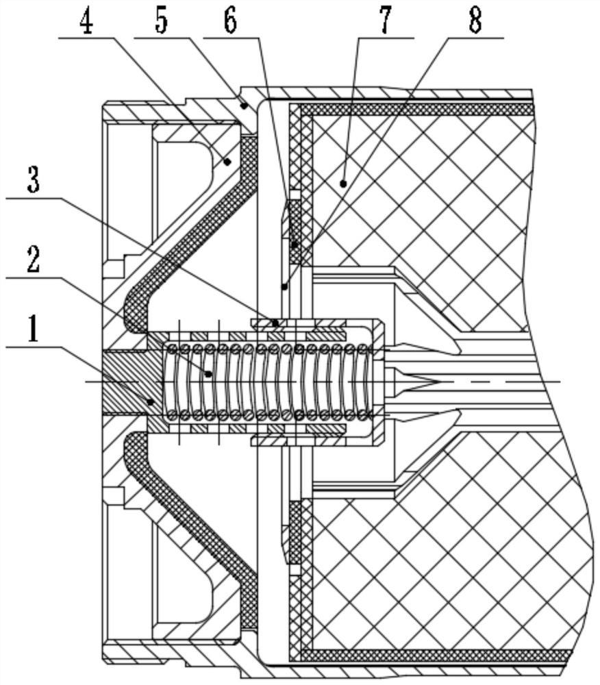
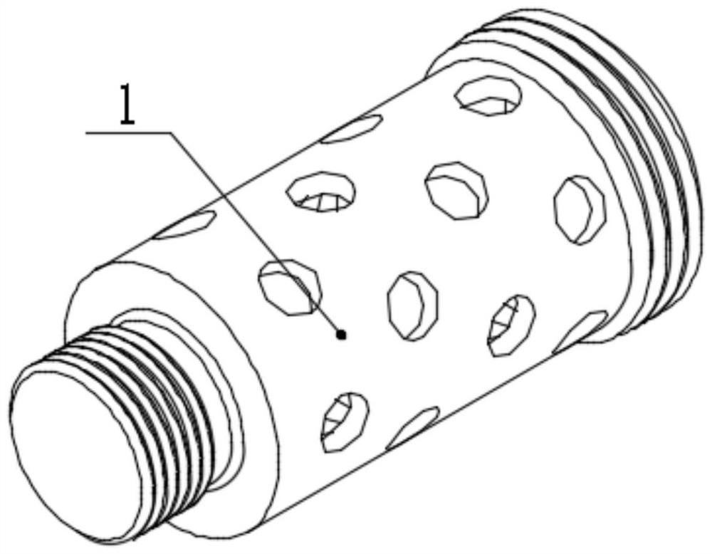
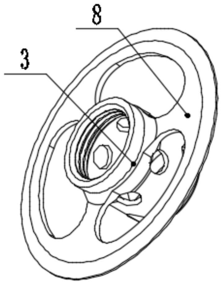
[0025] like Figures 1 to 3 As shown in the figure, the present embodiment provides a solid rocket motor free-filling grain compression structure, including a combustion chamber 5, and the combustion chamber 5 is sequentially provided with a blocking cover 4, a conduit 1, and a grain compression ring 3 from left to right. And free-filling powder column 7, a drug pressing spring 2 is arranged in the conduit 1, one end of the conduit 1 is threadedly connected with the blocking cover 4, and the other end is slidably connected with the drug column pressing ring 3.

[0026] The use process of the present invention is as follows:

[0027] Put the medicine compression spring 2 in the catheter 1, and the medicine column compression ring 3 compresses the medicine compression spring 2 and screwed into the catheter 1 until the medicine column compression ring 3 is sheathed outside the catheter 1 and moves freely. Next, screw the conduit 1 into the central thread of the cap 4 . Finally,...

Embodiment 2

[0029] The right end of the catheter 1 is provided with an external thread, the left end of the drug column pressing ring 3 is provided with an internal thread matching the external thread, and the inner wall of the drug column pressing ring 3 on the right side of the internal thread is a smooth surface.

[0030] After the grain compression ring 3 is screwed into the outer thread of the catheter 1, it can be sleeved on the catheter 1 and move freely, and at the same time, it will not fall off due to the resistance of the thread. This also ensures that the grain compression ring 3 can move freely with the deformation of the grain compression spring 2 and the grain and has a certain pre-tightening force.

[0031] Other structures of this embodiment are the same as those of Embodiment 1.

Embodiment 3

[0033] The side wall of the catheter 1 is provided with a number of first ventilation holes, the first ventilation holes communicate with the inner cavity of the blocking cover 4, and the right end face and the side wall of the grain compression ring 3 are provided with a number of second ventilation holes, and the grain pressure The outer surface of the tightening ring 3 is provided with a medicine pressing surface 8 specially used for pressing the freely packed grain 7 . The first vent hole communicates with the second vent hole, and the second vent hole communicates with the free-filling grain column 7 .

[0034] The first vent hole and the second vent hole are provided mainly to facilitate the circulation of gas.

[0035] Other structures of this embodiment are the same as those of Embodiment 1.


PUM


Abstract

The invention proposes a solid rocket motor free-filling powder column pressing structure and a use method, which solves the problem of abnormal internal ballistics caused by the spring falling off during the working process of the engine in the prior art. A solid rocket motor free-filling powder-column pressing structure comprises a combustion chamber, wherein from left to right in the combustion chamber, a blocking cover, a guide tube, a powder-column compression ring and a free-loading powder-column are arranged in sequence, and a drug-pressing spring is arranged in the guide tube. One end of the catheter is threadedly connected with the plug cover, and the other end is slidably connected with the medicine column compression ring. Using the solid rocket motor free-filling grain-pressing structure of the present invention, the grain-pressing spring can press the free-filling grain through the grain-pressing ring; Damage to the packed grain. Since the compression spring is fixed in the tube of the compression spring, the gas will not be carried out of the engine during the working process of the engine, which will cause abnormal ballistics in the engine.

Description

technical field [0001] The invention relates to the technical field of solid rocket motor charging, in particular to a solid rocket motor free-filling grain column pressing structure and a use method. Background technique [0002] In a grain free-packed solid rocket motor, the grain is free within the engine. Therefore, the grain column must be fixed at the front and rear ends of the grain column, and at the same time, the length change of the grain column at high and low temperatures must be considered. Generally, the rear end is fixed with a rigid grain blocking structure, and the front end is fixed with an elastic support structure to adapt to the grain column. Thermal expansion stress at high and low temperature. The elastic elements of the front-end elastic support structure mostly use springs. However, the springs are easy to break and fall off during the working process of the engine. During the falling process, the internal ballistic curve of the engine will be abno...

Claims


Application Information

Patent Timeline
Patent Type & Authority Patents(China)
IPC IPC(8): F02K9/24F02K9/34F02K9/10
CPCF02K9/24F02K9/34F02K9/10
Inventor 刘冬梅王锋马东亚张文雨赵倩倩吴建伟冯易周周志勇李阳阳贾致
Owner 南阳北方向东工业有限公司
Why Eureka
Eureka Blog
Learn More