Eureka AIR delivers breakthrough ideas for toughest innovation challenges, trusted by R&D personnel around the world.

Breaker data waveform detection acquisition device and acquisition method

A waveform detection and acquisition device technology, which is applied in the field of circuit breaker data waveform detection and acquisition devices, can solve problems such as cost increase, waveform lag, and delay, and achieve the effects of simplifying hardware circuits, reducing hardware costs, and preventing high-resistance floating

Pending Publication Date: 2021-10-08
JIANGSU STATE GRID AUTOMATION TECH
View PDF0 Cites 0 Cited by
  • Summary
  • Abstract
  • Description
  • Claims
  • Application Information

AI Technical Summary

Problems solved by technology

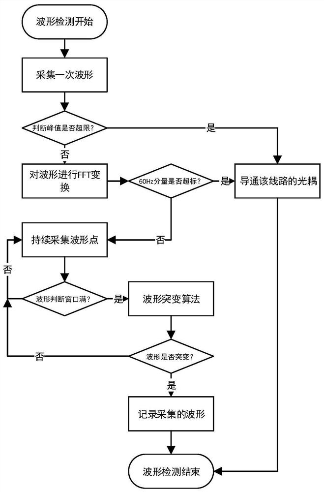
The traditional waveform acquisition method has the following disadvantages: 1) The number of components is large, and three-phase circuit breakers often have three independent acquisition circuits. The large number of components increases the cost, and the large number of components makes the device larger and difficult to integrate It is difficult to realize a smart circuit breaker with a high degree of integration inside the circuit breaker; 2) The position change of the auxiliary node of the circuit breaker and the transmission of the optocoupler have delay characteristics. When the trigger signal of the auxiliary node is used to trigger waveform acquisition, waveform lag or even missed acquisition is prone to occur 3) Without the corresponding waveform analysis function, it is impossible to accurately judge whether the collected waveform is the target waveform, and can only rely on the trigger signal to collect

Method used


Image

  • Breaker data waveform detection acquisition device and acquisition method
  • Breaker data waveform detection acquisition device and acquisition method
  • Breaker data waveform detection acquisition device and acquisition method

Examples


Embodiment

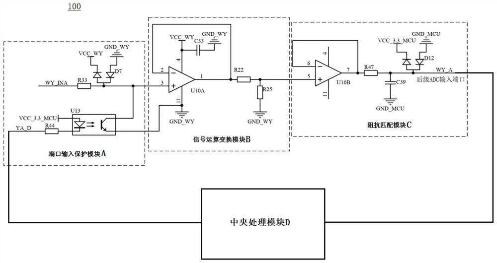
[0036] Please refer to figure 1 , this embodiment is a circuit breaker data waveform detection and acquisition device 100, which includes a port input protection module A, a signal transport conversion module B, an impedance matching module C and a central processing module D.

[0037] The port input protection module A is responsible for protecting the input terminal from being damaged when subjected to overvoltage. The signal transport transformation module B is responsible for transforming the amplitude of the input signal. The impedance matching module C is responsible for matching the input impedance of the subsequent ADC to make the acquisition of the ADC more accurate. The central processing module D is responsible for detecting the input signal and judging whether to collect and save it.

[0038] The port input protection module A includes an external sensor signal input terminal WY_INA, a first Schottky diode D7 , a first resistor R33 , an optical coupler U13 and a s...


PUM


Abstract

The invention discloses a breaker data waveform detection and acquisition device and acquisition method. The breaker data waveform detection and acquisition device comprises a port input protection module, a signal transmission and transformation module, an impedance matching module and a central processing module. The port input protection module comprises an external sensor signal input end, a first Schottky diode, a first resistor and an optical coupler; the signal transmission and conversion module comprises a first operational amplifier, a third resistor and a fourth resistor; the impedance matching module comprises a second operational amplifier and a second Schottky diode; an external sensor signal input end is connected with the output end of the first Schottky diode in parallel through the first resistor and then is divided into two paths, one path is connected to the in-phase output end of the first operational amplifier, the other path is connected to one input end of the optical coupler, and the optical coupler and the corresponding output end of the optical coupler are grounded and short-circuited. Only effective waveforms are collected, miniaturization design is achieved, the device can be integrated into a circuit breaker, and possibility is provided for achieving an intelligent circuit breaker.

Description

【Technical field】 [0001] The invention belongs to the technical field of waveform acquisition, in particular to a circuit breaker data waveform detection and acquisition device and acquisition method. 【Background technique】 [0002] At present, the demand for intelligent circuit breakers is increasing day by day. In order to meet the needs of intelligent circuit breakers, a variety of circuit breaker data acquisition devices have appeared on the market. Existing data acquisition devices include internal core circuits, basic signal scaling and acquisition trigger circuits. An external trigger signal is required to trigger waveform acquisition. When the position of the circuit breaker changes, the trigger signal will trigger the device for waveform acquisition and storage. The traditional waveform acquisition method has the following disadvantages: 1) The number of components is large, and three-phase circuit breakers often have three independent acquisition circuits. The larg...

Claims


Application Information

Patent Timeline
Patent Type & Authority Applications(China)
IPC IPC(8): G01R31/327
CPCG01R31/327
Inventor 卢菁锋姜万东樊越骁王晓堃庄如陈家乐
Owner JIANGSU STATE GRID AUTOMATION TECH
Why Eureka
Eureka Blog
Learn More