Tower inspection route design method

A route design and pole tower technology, which is applied in three-dimensional position/channel control, vehicle position/route/height control, instruments, etc., can solve the problems of inconsistent order of aerial photography points on inspection routes, low level of intelligence, aerial image naming, etc. , to achieve the effect of reducing the workload of manual intervention, improving the level of intelligence, improving efficiency and accuracy

Active Publication Date: 2021-10-08
WUHAN UNMAP REMOTE SENSING TECH CO LTD
View PDF19 Cites 0 Cited by
  • Summary
  • Abstract
  • Description
  • Claims
  • Application Information

AI Technical Summary

Problems solved by technology

Some companies in the market have done some work on the refined inspection route design technology of overhead transmission lines, but in the existing UAV inspection route design technology, it is necessary to manually select the shooting target point and manually name the tower shooting target point name The Nai Zhang Tower inspection route requires a lot of manual editing. The order of aerial photography points on the inspection route does not meet the requirements of the State Grid standard, and the aerial images cannot be automatically named according to the State Grid standard. The efficiency of patrol route design is low

Method used


Image

  • Tower inspection route design method
  • Tower inspection route design method
  • Tower inspection route design method

Examples


Embodiment 1

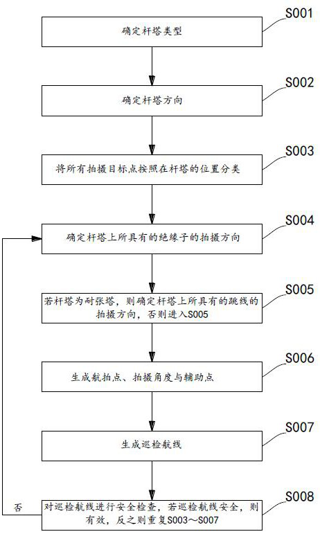
[0064] Such as figure 1 As shown, a method for designing a tower inspection route includes the following steps:

[0065] S001, determine the tower type;

[0066] S002. Determine the direction of the tower;

[0067] S003, classify all shooting target points according to their positions on the tower;

[0068] S004. Determine the shooting direction of the insulators on the tower;

[0069] S005. If the tower is a strain-resistant tower, determine the shooting direction of the jumper on the tower, otherwise go to S006;

[0070] S006. Generate aerial photography points, shooting angles and auxiliary points;

[0071] S007, generate the inspection route;

[0072] S008. Carry out a safety check on the inspection route. If the inspection route is safe, it is valid; otherwise, repeat S003-S007.

Embodiment 2

[0074] This embodiment is a further improvement on the basis of embodiment 1, specifically as follows:

[0075] For step S002, it is specifically:

[0076] According to the attribute information of the shooting target point, the coordinates of the left and right ground points on the tower are obtained, and the direction of the tower is obtained by calculating the coordinates of the left and right ground points.

Embodiment 3

[0078] This embodiment is a further improvement on the basis of embodiment 1 or 2, specifically as follows:

[0079] S003 is specifically:

[0080] Through azimuth calculation, the shooting target point on the left side of the left ground line is set as the left point of the tower, the shooting target point between the left and right ground lines is set as the middle point, and the point on the right side of the right ground line is set as the right point of the tower. After the points are classified according to the position of the tower, the aerial photography point of the optimal route can be designed according to the position of the shooting target point, so as to improve the inspection efficiency.


PUM


Abstract

The invention relates to a tower inspection route design method. The method comprises the following steps: S001, determining the type of a tower; S002, determining the direction of a tower; S003, classifying all shooting target points according to the positions of the shooting target points on the tower; S004, determining the shooting direction of the insulator on the tower; S005, if the tower is a strain tower, determining the shooting direction of a jumper wire on the tower, otherwise, entering S006; S006, generating an aerial photographing point, a photographing angle and an auxiliary point; S007, generating an inspection route; and S008, performing safety inspection on the inspection route, if the inspection route is safe, determining that the inspection route is effective, otherwise, repeating the steps S003-S007. The method has the beneficial effects that the efficiency and accuracy of unmanned aerial vehicle electric power refined inspection route planning are improved, and the intelligent level of unmanned aerial vehicle electric power inspection is improved to a great extent.

Description

technical field [0001] The invention relates to the field of line inspection, in particular to a design method for a tower inspection route. Background technique [0002] In recent years, the power industry has begun to use drones to inspect power lines in large areas. Because drones can go to places that are inaccessible or inconvenient for inspectors, they gradually liberate inspectors from high-intensity physical labor and become The best tool for inspectors to efficiently and safely complete inspection operations. However, in practical applications, external conditions such as control level, strong wind, strong light, signal interference and PTZ error affect the accuracy of inspection data. In the actual transmission line UAV inspection application, a large number of pilots are required to control the UAV to the operation site to perform inspection tasks, and the level of pilot control directly determines whether the inspection quality is up to standard, and the operati...

Claims


Application Information

Patent Timeline
Patent Type & Authority Applications(China)
IPC IPC(8): G05D1/10
CPCG05D1/106Y04S10/50
Inventor 罗祥勇郑安武李西林薛艳丽张田凤王立淑胡光崔浪浪齐艳青
Owner WUHAN UNMAP REMOTE SENSING TECH CO LTD
Why Eureka
Try Eureka