Efficient heat dissipation battery pack structure

A battery pack, high-efficiency technology, applied in the direction of secondary batteries, circuits, electrical components, etc., can solve the problems of less cycle times, low energy density ratio, poor heat dissipation, etc., and achieve the effect of improving heat transfer and good heat dissipation

Active Publication Date: 2021-10-08
湖北轼诚科技有限公司
View PDF15 Cites 0 Cited by
  • Summary
  • Abstract
  • Description
  • Claims
  • Application Information

AI Technical Summary

Problems solved by technology

[0002] At present, lead-acid batteries are mostly used as energy storage batteries. Lead-acid batteries have disadvantages such as large volume, low energy density ratio, less cycle times, and no environmental protection. Lithium battery energy storage is gradually accepted by the market; with the development of industry, lithium batteries There will be more and more application scenarios, such as emergency power supply, 5G communication, home energy storage, etc.; the existing modular cylindrical cells adopt a layered structure, which has the advantages of simple structure and safety
[0003] However, the current lithium battery and the matching box of the lithium battery have certain deficiencies. For example, the module structure of the battery pack is a stacked structure, and the heat dissipation capability is poor. , Turning on the water-cooling structure in the case of unnecessary heat dissipation will increase the loss of the battery. At the same time, the heating structure that maintains the operating temperature of the battery must also work, thereby greatly increasing the loss of the battery

Method used


Image

  • Efficient heat dissipation battery pack structure
  • Efficient heat dissipation battery pack structure
  • Efficient heat dissipation battery pack structure

Examples


Embodiment Construction

[0028] The following will clearly and completely describe the technical solutions in the embodiments of the present invention with reference to the accompanying drawings in the embodiments of the present invention. Obviously, the described embodiments are only some, not all, embodiments of the present invention.

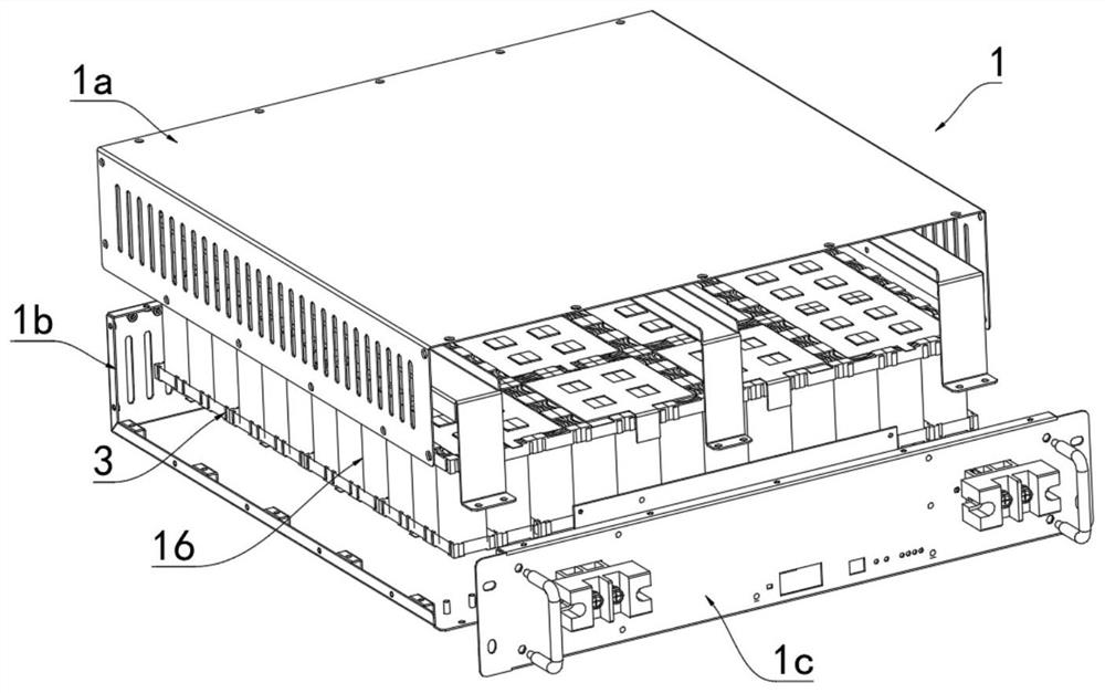
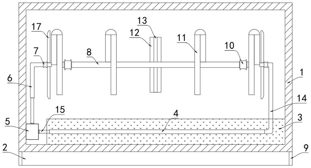
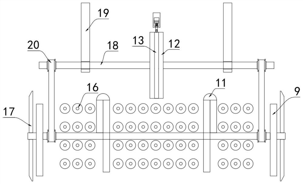
[0029] refer to Figure 1-6 , a high-efficiency heat dissipation battery pack structure, including a battery box 1, wherein the battery box 1 includes an upper box cover 1a, a lower box body 1b, and a panel 1c, and the upper box cover 1a, lower box body 1b, and panel 1c are composed of two pairs are connected by bolts, and a positive terminal and a negative terminal are installed on the panel 1c, then a positive current collector and a negative current collector corresponding to the positive terminal and the negative terminal are installed on the battery pack 16 .

[0030] The inner bottom of the battery box 1 is equipped with a thermally conductive silica gel plate ...


PUM


Abstract

The invention discloses an efficient heat dissipation battery pack structure which comprises a battery box, a heat conduction silica gel plate is installed at the inner bottom of the battery box, a battery pack is installed on the heat conduction silica gel plate, two supports are fixedly connected to the inner wall of the battery box, and a rotating rod rotationally connected with the two supports jointly penetrates through the two supports. A temperature control autorotation mechanism is installed on the rotating rod, a rotating pipe which penetrates through the battery pack and does not abut against the battery pack is arranged in the box body, four disc-shaped heat exchange pipes communicated with the rotating pipe are installed on the rotating pipe, pumping heat exchange mechanisms are installed between the two ends of the rotating pipe and the battery box, and a mounting frame is fixedly connected to the bottom of the battery box. Effective and efficient heat dissipation of the battery pack can be achieved, meanwhile, temperature control over work of the water pump can be achieved, loss of electric energy of the battery pack is reduced, internal circulation of air in the battery box can be achieved, and heat dissipation between batteries in the battery pack is further improved.

Description

technical field [0001] The invention relates to the technical field of battery pack structures, in particular to a battery pack structure with high heat dissipation. Background technique [0002] At present, lead-acid batteries are mostly used as energy storage batteries. Lead-acid batteries have disadvantages such as large volume, low energy density ratio, less cycle times, and no environmental protection. Lithium battery energy storage is gradually accepted by the market; with the development of industry, lithium batteries There will be more and more application scenarios, such as emergency power supply, 5G communication, home energy storage, etc.; the existing modular cylindrical cells adopt a layered structure, which has the advantages of simple structure and safety. [0003] However, the current lithium battery and the matching box of the lithium battery have certain deficiencies. For example, the module structure of the battery pack is a stacked structure, and the heat...

Claims


Application Information

Patent Timeline
Patent Type & Authority Applications(China)
IPC IPC(8): H01M10/613H01M10/6554H01M10/6556H01M10/6568H01M10/6565H01M10/635H01M10/653
CPCH01M10/613H01M10/6554H01M10/6556H01M10/6568H01M10/6565H01M10/635H01M10/653Y02E60/10
Inventor 杨一青
Owner 湖北轼诚科技有限公司
Why Eureka
Try Eureka